Key Takeaways
- EWIS Physical Hazard Assessment (PHA) is an important part complete EWIS risk assessments.
- Circuit protection, voltage, protection type, proximity to aircraft components all elements that must be considered.
- Lectromec services and software tools perform EWIS risks assessments faster and with more value than any other assessment technique.
Aircraft system safety assessments are not a new concept. These safety assessments have a defined process for evaluating an aircraft which involve identifying its failure modes, top-level events, and eventual means to achieve an unsafe condition. Documents such as the SAE ARP4761 provide guidelines and methods for conducting the safety assessment process on civil airborne systems and equipment.
To follow the typical development cycle, the aircraft failure hazard assessment (FHA) is followed by the system failure hazard assessment and performed in parallel with the preliminary system safety assessments (PSSAs). This then evolves into the system safety assessments (SSA) and common cause analyses (CCAs). For those with a systems reliability background, this should all be second nature. For the rest of the community, these are often terms that we come across because of our work in this field.
The Age of EWIS
It was not until 2000 when the idea of SSA involving the electrical wiring interconnect system (EWIS) became an idea that could be implemented. As part of some of the early work in this area, Lectromec developed a first of its kind and unique EWIS risk assessment tool with the FAA. This tool had to address two areas – the functional impact of EWIS failure and the physical impact of EWIS failure. In some sense, an aircraft EWIS physical hazard assessment had to be done.
In this article, we discuss the EWIS physical hazard assessment, why it is not a straightforward process, and what needs to be considered as part of an overall aircraft system evaluation and system certification.
Physical Hazard Assessment
A physical hazard assessment (PHA) looks at the areas of the aircraft design that can be impacted through physical damage. Considering the failure impacts of a hydraulic line, a hydraulic tube rupture will likely cause a loss of control of a system sub-component control (e.g. it may not be possible to activate a landing gear or flight control surface). From a physical hazard assessment view, the tube rupture might cause high-pressure fluid to escape and damage to the nearby components. Those nearby components might be fans that no longer can operate, electrical equipment now flooded with hydraulic fluid, or damaged wiring due to the high-pressure fluid.
Going back to an EWIS perspective, the physical hazard assessment has a lot in common with a ruptured hydraulic line. In particular, the physical hazard assessment with EWIS must factor in the potential impact of electrical arcing and the susceptibility of nearby components to this electrical arcing. Some aircraft components, such as the aircraft structure, are resilient to electrical arcing. Other aircraft components, such as hydraulic tubes, are susceptible to damage from electrical arcing events. For this reason, it is important to identify the components near the EWIS throughout the aircraft. This often means identifying the EWIS routing and proximity to the most at-risk components.
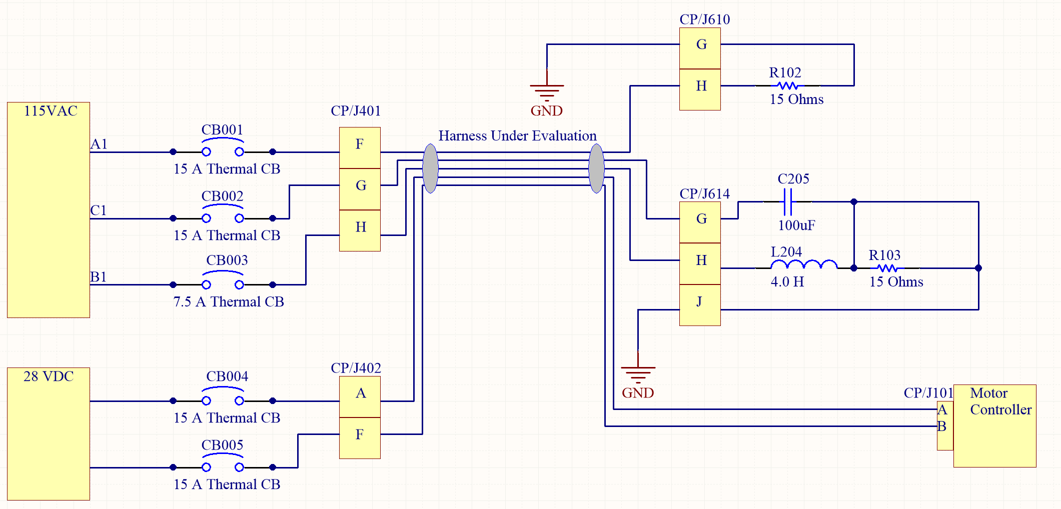
The physical hazard assessment of this circuit is not a simple process. Circuit resistance, circuit protection, wire gauge, and physical harness protection all impact the physical hazards. .
Not Straightforward
While it would be nice to simply say all power wiring must be at least one inch away from a component, and if it is, then it falls outside of the area of concern. Unfortunately, this is not the case. There are several factors that must be considered as part of a EWIS physical hazard assessment.
#1: Harness Size and Composition: A wire harness consisting of several wires with a variety of protection systems (e.g. thermal protection, solid state power controllers, etc.) will likely have a different separation requirement than a harness with the same configuration but located in a different part of the aircraft. Those that have been following Lectromec articles know that we regularly write about the potential impacts of electrical arcing and all the factors influencing the safe separation distance. Because of the complexity of modern aircraft EWIS, the safe separation distance will likely change over the length of a given wire harness.
#2: Nearby Components: Different aircraft components have different thresholds of damage before electrical arcing can cause an impact. Research by the US Air Force has shown that very short arcing durations (< 100 ms) directly to hydraulic tubes can cause rupture. The reaction speed of power controllers/circuit protection must be extremely fast to mitigate this possibility of damage. Further, different target types (e.g. aluminum hydraulic tubes, nearby wire harnesses, etc.) have different safe separation thresholds.
#3 Circuit Protection: Circuit protection has a significant impact on the duration of arcing events. It should not be assumed when performing an EWIS physical hazard assessment that the circuit protection will activate as quickly as identified in the standard thermal trip curves. The complexity and chaotic nature of arcing events makes this a very challenging task.
Considerations
So, what needs to be considered with an aircraft EWIS physical hazard assessment? At the very least, the following items should be considered
Co-location: The co-location of wiring harnesses with aircraft components should be identified. This includes aircraft equipment, hydraulic lines, fuel system components, and other wiring harnesses. Further, it should be identified which part of the wiring harness these components are near as it makes it possible to later examine the separation distance vis-à-vis the potential damage caused by a given wire harness.
Harness Contents: Modular wire harnesses are convenient for fabrication, installation, and maintenance. However, this does not mean that the contents of a wire harness are uniform. As part of a physical hazard assessment, the routing within these harnesses should be identified to make it easy to identify the potential physical hazard.
Distance from power source: The distance from the power source will have an impact on the amount of energy available and the circuit breaker response time. This should be identified for each of the power wires within the wire harness.
Make it easy on yourself
The physical hazard assessment of an aircraft EWIS is a complicated task. Because so much data and knowledge must be brought together (synthesized) to properly identify physical risks, it is highly recommended to take advantage of existing tools. Service offerings like Lectromec’s Arc Damage Modeling Tool (ADMT) and EWIS Risk Assessment Tool (EWIS RAT) can reduce the manual efforts more than 80%. Lectromec has used these tools as part of other aircraft assessment efforts and were used in the first-of-its-kind EWIS risk assessment of an in-service vehicle.
The technology exists to avoid large scale manual effort as part of EWIS physical hazard assessments and take advantage of the last 30 years of wiring system failure event research. Lectromec can help address your fleet’s EWIS risk assessment and physical hazard assessment needs.

Michael Traskos
President, Lectromec
michael.traskos@lectromec.comMichael has been involved in wire degradation and failure assessments for more than a decade. He has worked on dozens of projects assessing the reliability and qualification of EWIS components. Michael is an FAA DER with a delegated authority covering EWIS certification and the chairman of the SAE AE-8A EWIS installation committee.