Key Takeaways
- EWIS system safety relies on well established risk assessment fundamentals.
- Risk assessment is dependent on quantifying failure probability and failure severity.
- Tools, such as Lectromec’s EWIS RAT, can expedite EWIS risk assessment.
Of the regulations encapsulating the 25.17XX EWIS group, none is more complicated than 25.1709. This regulation, consisting of only 31 words, can be the result of thousands of hours of labor, hundreds of pages of documentation, and requiring inputs from just about every system group working on the vehicle. If you step back from the regulation and ask, “What is necessary to show compliance?” it comes down to several factors.
Here, we review some of the basic principles of 25.1709, where it impacts and interacts with other systems in the vehicle.
What is the regulation?
These 31 words carry a lot of weight and they hide a lot of the complexity rooted in risk assessment concepts.
25.1709 System safety: EWIS.
Each EWIS must be designed and installed so that:
(a) Each catastrophic failure condition –
(1) Is extremely improbable; and
(2) Does not result from a single failure.
(b) Each hazardous failure condition is extremely remote.
As covered in previous Lectromec articles (here and here), risk assessment relies on identifying the probability of failure and the severity of failure. Regulation “Item A” requires that catastrophic EWIS failure events EWIS must have a failure probability of “extremely improbable”.
Item B requires hazardous EWIS failure events have a failure probability of extremely remote or better. For those unfamiliar with these terms, they have specific meaning in the aerospace industry and have specific values.
Failure Levels
The following tables are taken directly from AC 25.1701-1 and the FAA System Safety Handbook
|
Term |
Explanation |
|
No Safety Effect |
Failure conditions that would have no effect on safety, for example failure conditions that would not affect the operational capability of the airplane or increase flightcrew workload. |
|
Minor |
Failure conditions that would not significantly reduce airplane safety, and involve flightcrew actions that are well within their capabilities. For example, minor failure conditions may include: – a slight reduction in safety margins or functional capabilities; – a slight increase in flightcrew workload, such as routine flight plan changes; or – some physical discomfort to passengers or cabin crew. |
|
Major |
Failure conditions that would reduce the capability of the airplane or the ability of the flightcrew to cope with adverse operating conditions to the extent that there would be, for example: – a significant reduction in safety margins or functional capabilities; – a significant increase in flightcrew workload or in conditions impairing flightcrew efficiency; – discomfort to the flightcrew; or – physical distress to passengers or cabin crew, possibly including injuries. |
|
Hazardous |
Failure conditions that would reduce the capability of the airplane or the ability of the flightcrew to cope with adverse operating conditions to the extent that there would be, for example: – a large reduction in safety margins or functional capabilities; – physical distress or excessive workload such that the flightcrew cannot be relied upon to perform their tasks accurately or completely; or – serious or fatal injuries to a relatively small number of persons other than the flightcrew. |
|
Catastrophic |
Failure conditions that would result in multiple fatalities, usually with the loss of the airplane. (NOTE: A catastrophic failure condition was defined differently in previous versions of § 25.1309 and in accompanying advisory material as “a failure condition that would prevent continued safe flight and landing.” |
|
Identification |
Qualitative Description |
|
Probable |
Qualitative: Anticipated to occur one or more times during the entire system/operational life of an item. Quantitative: Probability of occurrence per operational hour is greater that 1 x 10⁻⁵ |
|
Remote |
Qualitative: Unlikely to occur to each item during its total life. May occur several time in the life of an entire system or fleet. Quantitative: Probability of occurrence per operational hour is less than 1 x 10⁻⁵ , but greater than 1 x 10⁻⁷ |
|
Extremely Remote |
Qualitative: Not anticipated to occur to each item during its total life. May occur a few times in the life of an entire system or fleet. Quantitative: Probability of occurrence per operational hour is less than 1 x 10⁻⁷ but greater than 1 x 10⁻⁹ |
|
Extremely Improbable |
Qualitative: So unlikely that it is not anticipated to occur during the entire operational life of an entire system or fleet. Quantitative: Probability of occurrence per operational hour is less than 1 x 10⁻⁹ |
A common tool used for visualizing the failure probability and failure severity is a risk assessment matrix (MIL-STD-882). In this, the severity of failure is shown along the horizontal axis and the probability of failure is shown along the vertical axis. This matrix is a means to visually present the concept of risk assessment and the trade-offs between system reliability and failure severity. Ideally, the goal is to ensure that the probability of system failure is relatively low, and often this is achieved by higher-quality parts, better design, and/or system redundancy [see how this is applied to aging aircraft].
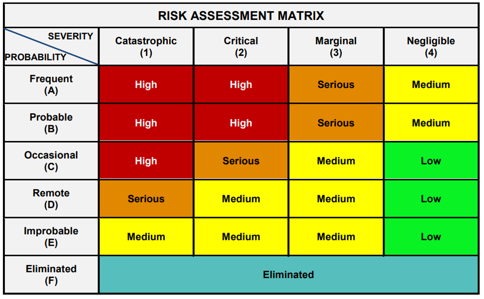
Example risk assessment matrix. Source: MIL-STD-882.
Mathematically, for a risk to be fully eliminated requires that it physically cannot happen (think of water catching fire). From a practical perspective, several layers of redundancy can achieve the same objective.
Redundancy and impact on Risk
The idea of system redundancy is that if one component fails every 1000 hours, the probability of failure is roughly 1 in 1000 or 10-3 failures per flight hour. If there is a backup system supporting this function that has the same failure probability of 10-3, then the combined system reliability can be said to be 10-6 failures per flight hour. This improved failure rate of the combined system is possible if the components and supporting systems are completely independent.
If the systems rely on a single power source, that potentially reduces the reliability of the system. If the two devices rely on exactly the same input, the reliability potentially is reduced. From an EWIS perspective, if the system wiring is co-located in the same wiring harness, runs through the same connector, or could be damaged by a single event e.g. tire burst, then this also reduces the combined reliability of the two systems. This last point of EWIS separation is what is highlighted in a couple of the EWIS regulations.
Reliability
A single failure cannot lead to a catastrophic failure condition. From the perspective of 25.1709, that means that EWIS supporting redundant systems cannot be co-located. They cannot be placed in the same wire harness, and they cannot be routed in the same connector. To do otherwise, would violate the intention of the regulation.
So what is necessary to actually show compliance? As a starting point, advisory circular (AC) 25.1701–1 provides a good description on what needs to be considered to show compliance. The advisory circular breaks up the elements of 25.1709 into two separate domains: physical and functional impact. Lectromec has a couple articles devoted to discussing these areas of 25.1709 and they are available here.
For those that are not looking to read another article, this comes down to ensuring that the physical separation is considered (much of this data is gathered to support 1707 requirements), and that the functional separation is also addressed (think single point failure). Much of the functional separation requires work with various systems groups and the system safety engineers to identify the functional impact of the EWIS failure.
Expedite results
So what can be done to expedite 25.1709 compliance documentation and evaluation? For one, understanding the requirements early in the project can have a great impact on reducing the long-term cost of EWIS evaluation. Second, Lectromec’s risk assessment tool can be used to evaluate wiring systems very quickly and reduce the total amount of labor needed. Contact Lectromec for details.

Michael Traskos
President, Lectromec
michael.traskos@lectromec.comMichael has been involved in wire degradation and failure assessments for more than a decade. He has worked on dozens of projects assessing the reliability and qualification of EWIS components. Michael is an FAA DER with a delegated authority covering EWIS certification and the chairman of the SAE AE-8A EWIS installation committee.