Key Takeaways
- Calculating the voltage drop is important to ensure proper functioning equipment.
- Just because 115VAC is applied to a circuit does not mean the attached equipment will “see” 115VC. The length and gauge of a wire will have an impact.
- There are well established methods to estimate voltage drop.
If voltage is applied to a circuit and the attached equipment does not turn on, then there is an issue with either the circuit or the applied voltage (assuming the device is fully functioning). Sometimes glossed over in circuit design, the length and gauge of a wire can impact the voltage to the load; this is known as “voltage drop”. Just as the current carrying capacity of a wire/wire harness is impacted by the system and environment, so too is the voltage drop.
In this article, we go over the idea of voltage drop, guidance on its application in design, and an example of quantifying the voltage drop on a wire/cable.
Voltage Drop
Wire conductors are not perfect electrical conductors, and because of this, there is energy loss along the wire. In past articles, we have addressed the conductor resistance from an ampacity perspective, and the conductor heating can only occur if there is conductor resistance. The total wire conductor resistance for a circuit may be small, but it is non-trivial. Depending on the circuit current, a 20AWG wire may be limited to a length of 50 feet or 400 feet.
Thankfully, there is guidance to help determine the voltage drop for a circuit.
Guidance
Perhaps one of the most easily referenceable documents the FAA has published is its AC 43-13. In addition to guidance on a great deal of system design concepts, it also provides guidance on addressing voltage drop. To quote AC 43-13-1B Section 11-48, “Wires must be sized to carry continuous current in excess of the circuit protective device rating, including its time-current characteristics, and to avoid excessive voltage drop.”

The maximum circuit voltage drop is defined so equipment designers know the performance expectations for their equipment. Source: FAA.
AC 43-13-1B provides a table on the allowable voltage drop for continuous operation and for intermittent operation. It is important to note that the chart does differentiate between allowable voltage drop for continuous and intermittent operation. To put this into perspective, AC 43-13-1B identifies an intermittent load as one whose operation is limited to not more than two minutes at a time. At no point in the AC is there any information about how frequently an intermittent circuit can be operated, but Lectromec suggests the duration between intermittent operations should be sufficiently long as to allow the circuit to return to ambient conditions (e.g. permit the wiring time to cool).
Table 11-6 shows the allowable voltage drop between a bus and the equipment ground. These values are in line with the expected performance values identified in system power quality documents such as MIL-STD-704. For a 115VAC system, the maximum allowable voltage drop for continuous operations is 4V; for intermittent, the maximum voltage drop is 8V.

Voltage drop by wire gauge, current, and system voltage. Source: FAA.
As with much of the AC 43-13-1B guidance, there is good information available, but it does not give the full picture. An example of this is the calculation of voltage drop for a circuit. The table and information presented in the AC is for tin plated wire. With silver- and nickel-plated wire conductors having lower resistance, the information in the AC is on the conservative side of the voltage drop calculations.
Voltage Derating
AC 43-13-1B does provide a chart for estimating the voltage drop, but since the chart can be quite confusing, we will run through an example that should hopefully make it easier to follow.
On the left side of the figure, there is a table showing the continuous circuit voltage for four different voltage levels (200, 115, 28, and 14). At the bottom of this table, the voltage drop levels of 7 V, 4 V, 1 V, and 0.5 V are shown corresponding to the maximum voltage drop allowed for the given voltage level. The center of this table shows the wire length necessary to achieve the voltage drop (bottom of table) for the system voltage (shown at the top of the table).
If, for example we have a circuit operating on a 16AWG wire and a continuous current of 10 A, then we first look for the wire gauge along the bottom horizontal axis and where it intersects with the diagonal lines coming from the top axis. In this 16AWG example, we look for the diagonal line that starts at the value “10” on the top axis. In the figure, this value intersects with the 16AWG vertical line indicating that the maximum wire length to limit the voltage drop to 4 V on a 115 V system would be 80 feet.

Source: FAA.
The figure also shows three other examples of an 8AWG wire at 20 A, 12AWG wire at 20 A, and 14AWG wire at 20 A. While each of these wire gauges can support a 20-amp load, the maximum allowable wire length is significantly impacted. In the case of a 14AWG wire carrying a 20-amp load, the figure suggests that the maximum wire length 115 V system is about 60 feet. Comparing this to an 8AWG wire, the maximum wire length is about 200 feet.
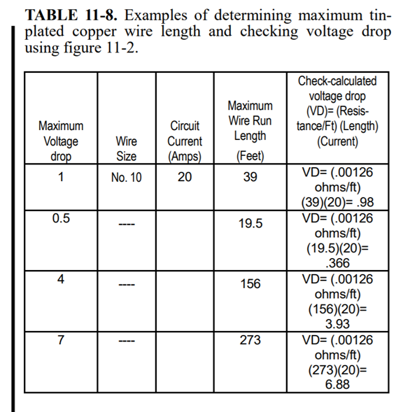
The following two figures, Table 11-7 and Table 11-8, show additional examples taken from AC 43-13-1B.
Design Impact
From a design perspective, this means that an EWIS engineer must balance both the current rating and ampacity of a wire harness with the voltage drop requirements. Furthermore, the analysis does show a very straightforward reason for selecting higher voltage systems. With higher voltage applications, the permitted voltage drop along the wire length is greater and allows for smaller gauge wires to carry voltage greater distances.
Source: FAA.
Conclusion
A circuit ’s voltage drop is as important as its ampacity. Thankfully for those looking to ensure their designs are within the performance tolerances stated in AC 43-13-1B can do it with fewer calculations and derating elements as ampacity.
For those looking to get more from their EWIS designs and ensure they match best practices, contact Lectromec. We have the breadth of experience and lab capabilities to address your EWIS challenges.

Michael Traskos
President, Lectromec
michael.traskos@lectromec.comMichael has been involved in wire degradation and failure assessments for more than a decade. He has worked on dozens of projects assessing the reliability and qualification of EWIS components. Michael is an FAA DER with a delegated authority covering EWIS certification and the chairman of the SAE AE-8A EWIS installation committee.