View Latest Blog Entries
Close
Categories
Testing & Assessment Certification Standard & Regulation Aging Wires & Systems Maintenance & Sustainment Management Conference & Report Protection & Prevention Research Miscellaneous Arcing
Popular Tags
Visual Inspection High Voltage AS50881 MIL-HDBK MIL-HDBK-525 FAR AS4373 Maintenance Electromagnetic Interference (EMI) FAR 25.1707 Wire System Arcing Damage
All Tags in Alphabetical Order
2021 25.1701 25.1703 abrasion AC 33.4-3 AC 43 Accelerated Aging accessibility ADMT Aging Systems AIR6808 AIR7502 Aircraft Power System aircraft safety Aircraft Service Life Extension Program (SLEP) altitude arc damage Arc Damage Modeling Tool Arc Fault (AF) Arc Fault Circuit Breaker (AFCB) Arc Track Resistance Arcing Arcing Damage AS22759 AS22759/87 AS23053 AS29606 AS4373 AS4373 Method 704 AS50881 AS5692 AS6019 AS6324 AS81824 AS83519 AS85049 AS85485 AS85485 Wire Standard ASTM B355 ASTM B470 ASTM D150 ASTM D2671 ASTM D8355 ASTM D876 ASTM F2639 ASTM F2696 ASTM F2799 ASTM F3230 ASTM F3309 ATSRAC Attenuation Automated Wire Testing System (AWTS) Automotive Avionics backshell batteries bend radius Bent Pin Analysis Best of Lectromec Best Practice bonding Cable Cable Bend cable testing Carbon Nanotube (CNT) Certification cfr 25.1717 Chafing Chemical Testing Circuit Breaker circuit design Circuit Protection cleaning clearance Coaxial cable cold bend collision comparative analysis Compliance Component Selection Condition Based Maintenance Conductor Conductor Testing conductors conduit Connector Connector rating connector selection connector testing connectors contacts Corona Corrosion Corrosion Preventing Compound (CPC) corrosion prevention Cracking creepage D-sub data analysis data cables degradat Degradation Delamination Derating design safety development diagnostic Dielectric breakdown dielectric constant Dimensional Life disinfectant Distributed Power System DO-160 dry arc dynamic cut through E-CFR electric aircraft Electrical Aircraft Electrical Component Electrical Power Electrical Testing Electrified Vehicles Electromagnetic Interference (EMI) Electromagnetic Vulnerability (EMV) Electrostatic Discharge EMC EMF EN2235 EN3197 EN3475 EN6059 End of Service Life End of Year Energy Storage engines Environmental Environmental Cycling environmental stress ethernet eVTOL EWIS certification EWIS Component EWIS Design EWIS Failure EWIS sustainment EWIS Thermal Management EZAP FAA FAA AC 25.27 FAA AC 25.981-1C FAA Meeting failure conditions Failure Database Failure Modes and Effects Analysis (FMEA) FAQs FAR FAR 25.1703 FAR 25.1707 FAR 25.1709 Fault fault tree Fixturing Flammability fleet reliability Flex Testing fluid exposure Fluid Immersion Forced Hydrolysis fuel system fuel tank ignition Functional Hazard Assessment functional testing Fundamental Articles Fuse Future Tech galvanic corrosion Glycol Gold Gold plating Green Taxiing Grounding hand sanitizer handbook Harness Design harness protection hazard Hazard Analysis health monitoring heat shrink heat shrink tubing high current high Frequency high speed data cable High Voltage High Voltage Degradation HIRF History Hot Stamping Humidity Variation HV connector HV system ICAs IEC 60851 IEC60172 IEEE immersion insertion loss Inspection installation installation safety Instructions for Continued Airworthiness insulating material insulating tape Insulation insulation breakdown insulation resistance insulation testing interchangeability IPC-D-620 ISO 17025 Certified Lab ISO 9000 J1673 Kapton Laser Marking life limit life limited parts Life prediction life projection Lightning lightning protection liquid nitrogen lithium battery lunar Magnet wire maintainability Maintenance Maintenance costs Mandrel mean free path measurement mechanical stress Mechanical Testing MECSIP MIL-C-38999 MIL-C-85485 MIL-DTL-17 MIL-DTL-23053E MIL-DTL-3885G MIL-DTL-38999 MIL-E-25499 MIL-HDBK MIL-HDBK-1646 MIL-HDBK-217 MIL-HDBK-454 MIL-HDBK-516 MIL-HDBK-522 MIL-HDBK-525 MIL-HDBK-683 MIL-STD-1353 MIL-STD-1560 MIL-STD-1798 MIL-STD-464 MIL-T-7928 MIL-T-7928/5 MIL-T-81490 MIL-W-22759/87 MIL-W-5088 MIL–STD–5088 Military 5088 modeling moon MS3320 NASA NEMA27500 Nickel nickel plating No Fault Found OEM off gassing Outgassing Over current Overheating of Wire Harness Parallel Arcing part selection Partial Discharge partial discharge at altitude Performance physical hazard assessment Physical Testing polyamide polyimdie Polyimide-PTFE Power over Ethernet power system Power systems predictive maintenance Presentation Preventative Maintenance Program Probability of Failure Product Quality PTFE pull through Radiation Red Plague Corrosion Reduction of Hazardous Substances (RoHS) regulations relays Reliability Research Resistance Revision C Rewiring Project Risk Assessment S&T Meeting SAE SAE Committee Sanitizing Fluids Secondary Harness Protection separation Separation Requirements Series Arcing Service Life Extension Severe Wind and Moisture-Prone (SWAMP) Severity of Failure shelf life Shield Shielding Shrinkage signal signal cable Silver silver plated wire silver-plating skin depth skin effect Small aircraft smoke Solid State Circuit Breaker Space Certified Wires Splice standards Storage stored energy superconductor supportability Sustainment System Voltage Temperature Rating Temperature Variation Test methods Test Pricing Testing testing standard Thermal Circuit Breaker Thermal Endurance Thermal Index Thermal Runaway Thermal Shock Thermal Testing tin Tin plated conductors tin plating tin solder tin whiskering tin whiskers top 5 Transient Troubleshooting TWA800 UAVs UL94 USAF validation verification video Visual Inspection voltage voltage differential Voltage Tolerance volume resistivity vw-1 wet arc white paper whitelisting Winding wire Wire Ampacity Wire Bend Wire Certification Wire Comparison wire damage wire failure wire performance wire properties Wire System wire testing Wire Verification wiring components work unit code

Conductor Resistance ASTM B193

Testing & Assessment

Key Takeaways
  • For many applications, resistance measurements are straight forward, but this is not always the case.
  • Low resistance measurements require special tool and techniques to get accurate measurements.
  • There are test methods to capture the impact of temperature on resistance.

The measurement of resistance seems to be a trivial task. Hook up a standard handheld multimeter with two probes and attach the probes to either side of the device or component that you want to measure. For the most part, this process works well. More correctly, for devices with resistances between 2 Ohms and 1M Ohm, this is a good technique, however, once the resistance values get really high or really low, the process becomes a little more complicated. While the basic physics remains the same (Voltage = Current * Resistance), getting the setup to correctly measure the component requires attention to detail.

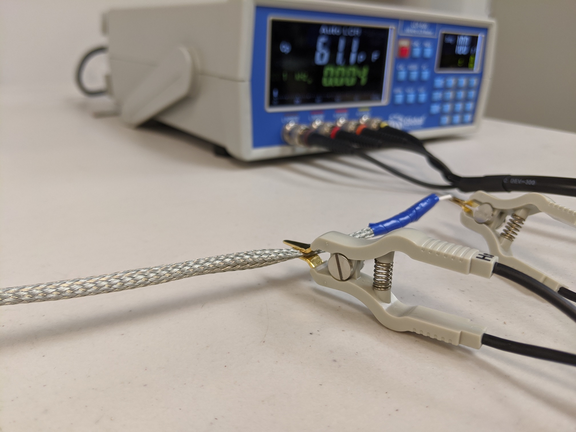
Where do handheld units fail?

The issue with most handheld meters is that the level of accuracy in the low range (0 – 100 Ohms) is limited to ±0.1 Ohms. This creates a measurement threshold for a lot of applications. If a conductor resistance measurement is performed on 3,000 feet of wire, the accuracy has a minimal impact. For example, 3,000 ft of 20AWG wire yields about 29.6 Ohms (maximum allowable resistance for 20AWG AS22759/18 wire). With an accuracy of ±0.1 Ohms, the uncertainty of resistance per foot is ±30 µOhms. Compare this to the measurement of 10 ft of 20AWG of the same specification; a handheld meter would measure about 0.1 Ohms, with the uncertainty of resistance of the 10 ft sample being ±0.1 Ohms. It is usually not preferable to have the measurement uncertainty to be equal to the measurement itself.

The handheld multimeter does tell you the continuity of the circuit for short wire lengths, it does not do a good job with providing an accurate measurement. Other techniques have to be employed for an accurate reading.

Low Resistance Measurements

One problem with any low resistance measurements is surface resistance. Many metal surfaces will develop an oxidization layer. This oxidization layer creates a high surface resistance; you may experience this when measuring a sheet of metal only to find a higher than expected resistance. The way to handle this is with a little bit of surface preparation. This can be done with cleaning or a little surface abrasion to break through the oxidization layer.

Making the Measurement

If using a two-point probe (such as what is commonly used with handheld multimeters), then it is necessary to also account for the probe resistance and the resistance wire to the measurement device. The best way to do this is connect the two probes together and record the resistance. This resistance is then subtracted from the sample resistance measurement.

When dealing with low resistance measurements, a four-point probe is preferred. A four-point probe is a special device based on a Kelvin bridge design. The basic idea is that both the current and voltage measurements are made to provide a high level of resistance measurement accuracy.

ASTM B193

There are many standards that cover the testing of conductors; the discussion here focuses on the ASTM B193. This standard, first released in 1987, is designed to handle the generalized means of test methods to address the wide needs of the wire/cable industry.

There are a couple elements of this test that are unique to testing conductors. The dimensional size of the cable under evaluation must be evaluated. This includes measurement of the specimen’s weight.

For testing, the sample is prepared by striping the insulation from both ends of the wire or cable. Depending on the sample, there are a couple means of test measurement:

Option #1: Attach the sample to the resistance measurement device and record the result. This is possible if the sample’s resistance is high or the equipment has a high accuracy.

Resistance measurements are a non-trivial task. Using the right equipment is necessary to achieve accurate results.

Option #2: If the first method is not viable, then an alternative method must be employed. The sample is attached to a current controlled DC power supply. The current through the sample is limited, and both the current and the voltage across the sample is recorded. While this method still employs ohms law, the use of a higher voltage and current allows for a better measurement of the sample.

With this method, it is important that the current remain at less than 10% of the wire’s rating. Doing so avoids conductor heating that will alter the resistance measurement.

Temperature Adjustment

In the ASTM B193 standard, a formula is provided to account for measurement at different temperatures. This formula is based on known properties of the conductor and its resistance response to different temperatures. For those materials that do not have a well-defined temperature relationship, there are methods to capture this parameter.

A test method has been developed by the SAE 8D thermal modeling task group; while it is not part of the current revision, the test method should be part of the AS4373 test standard in the next revision. In this test method, the wire is submerged into a temperature-controlled fluid. The fluid is used to ensure the wire is at thermal equilibrium when any resistance measurement is made.

Progressively, the temperature is increased, and the resistance measurements are made at several temperatures. From these measurements, a best fit curve is created so that the conductor resistance may be calculated at different temperatures.

Conclusion

Whether the test is performed in accordance with ASTM B193, ASTM D3032, or any other test method, testing the conductor resistance is the application of voltage and current to capture a conductor’s resistance value.

If you are looking for a lab to help you with you cable assessment needs, contact Lectromec. We have you covered.

Michael Traskos

Michael Traskos

President, Lectromec

Michael has been involved in wire degradation and failure assessments for more than a decade. He has worked on dozens of projects assessing the reliability and qualification of EWIS components. Michael is an FAA DER with a delegated authority covering EWIS certification and the chairman of the SAE AE-8A EWIS installation committee.