Key Takeaways
- Partial discharge is a phenomenon which causes damage over time within the imperfections of a wire/ cable insulation.
- Modern, high-voltage, aircraft design must consider the long term effects of partial discharge.
- A greater voltage differential between the inner conductor and the insulation of a wire construction creates conditions of higher susceptibility to partial discharge.
- Standard test methods exist to evaluate the partial discharge performance under high-voltage conditions.
Introduction
It started several years ago. At a US government, interagency S&T meeting that included industry representatives, a representative from the US Navy presented an important finding to the attendees. Namely, a review of the aerospace wire and cables standards did not have a means to verify the maximum operating voltage level. For decades, aircraft used 115VAC (208VAC line-to-line) power; new power systems changed that assumption and the dogmas of the low voltage past are inadequate for the high voltage present.
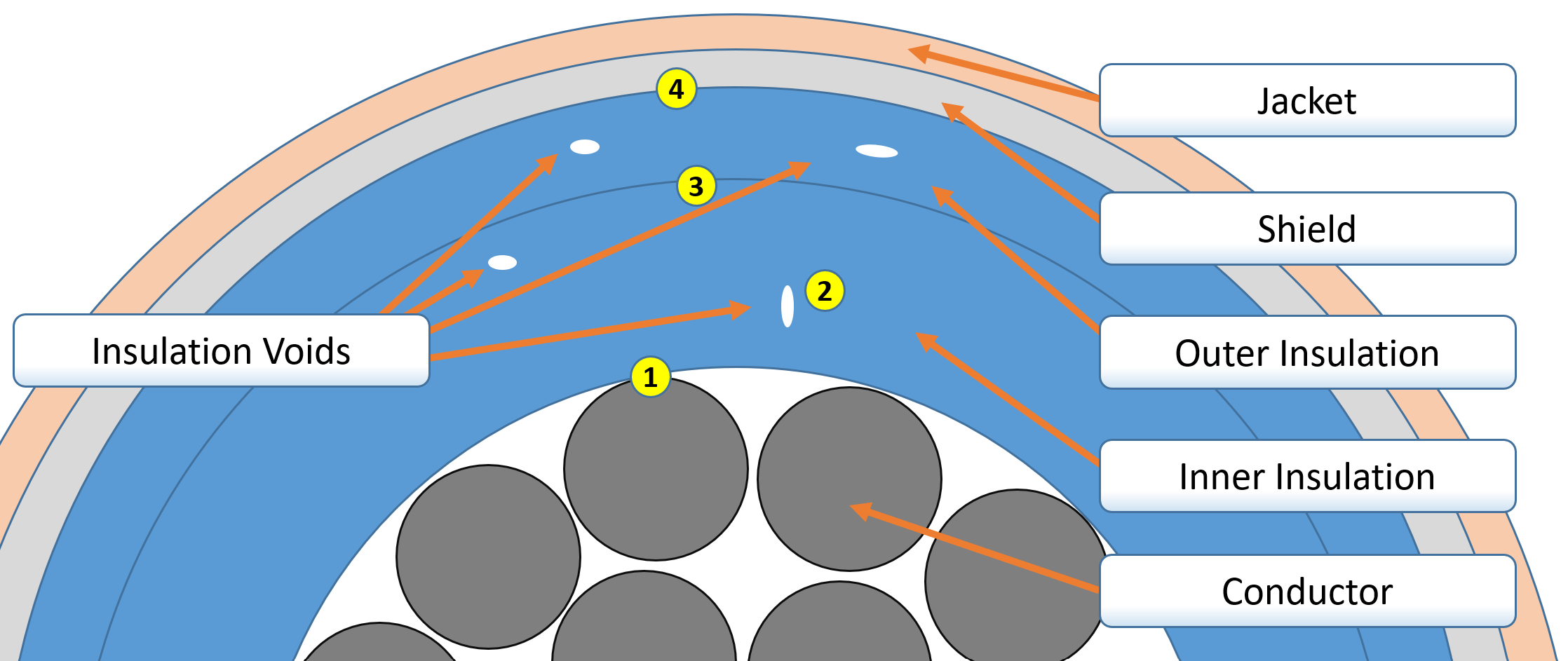
In this high-voltage present, wires and cables must address new challenges, perhaps the most notable is partial discharge (also referred to as corona). This article discusses the fundamentals of partial discharge, its impacts on wiring design, and test methods used to assess a component’s partial discharge performance. The PD may occur between (1) the conductor and insulation, (2) within void in the insulation, (3) between insulation layers, or (4) between the insulation surface and shield.
Partial discharge
Imperfections in a wire/ cable construction’s insulation result in voltage differentials which can lead to partial discharge.
Partial discharge is a phenomenon in which a voltage breakdown occurs across or through an insulator. Unlike an insulation breakdown, the insulation remains intact and still acts as a resistor, though it might be slightly damaged. Partial discharge may occur on the interface between the conductor and the insulation, within the insulation itself, or along the outer surface of the insulation. Where and at what voltage partial discharge occurs is dependent on construction.
How does it happen?
Partial discharge occurs when there is a sufficiently high voltage differential across an insulator. Think of a single uniform extruded wire insulation, from the outside, it looks like a nice smooth homogeneous insulator. In fact, there are likely tiny voids (air bubbles) in the insulation that occur during the fabrication process. Now sandwich that insulator between a conductor at voltage and ground plane. Within the insulation, there is a voltage gradient. For example, if the insulation is 10 mils thick (0.254 mm) and the voltage between the conductor and the ground is 1000V, then the voltage is 100V per mil (or about 4kV per mm).
Taking this one step further, if there is a 1mil void in the insulation, there will be a voltage differential high enough to result in a spark across that 1mil gap. For AC power systems, the voltage cycling will result in the discharge occurring above some threshold voltage and halting when the AC voltage falls below the voltage necessary to sustain the event. For DC systems, the voltage may never fall below the ‘extinction voltage’ resulting in consistent activity.
The partial discharge may also occur in the gap between the conductor and insulation or along the surface of the insulation where a voltage differential is present.
Although the partial discharge is a voltage breakdown, it is a low-energy event. Since the electrical path from the power source to ground (or line-to-line in multiple phase systems) includes the insulation, there is a large resistor in the circuit. A close parallel is to think of discharging a small capacitor into a circuit with a large resistance.
Consequences
Partial discharge, even at low energies, can cause insulation damage primarily through carbonization of the insulation. This carbonization is a very slow process, particularly when the voltage level is barely above the partial discharge inception voltage. The carbonization causes the insulation to slowly become semi-conductive until there is a conductive path finally resulting in insulation (dielectric) breakdown. Once that occurs, the event may be similar to an electrical arcing event if a significant voltage differential is present, or the event may be more benign if it occurs in the device or within the circuit where there is still an in-series electrical load (for example: between motor windings).
Speed of Failure
The speed of insulation degradation due to partial discharge is dependent on several factors including:
- System voltage
- System power frequency
- Waveform shape (e.g., sinusoidal versus pulse width modulation)
- Temperature
- Altitude (Discussed further in this article)
- Circuit noise (e.g., back EMF from relays)
- Component design
The combination of these factors and how they reduce component life is an area of ongoing research and for the last several years, Lectromec has been investigating the impact of these parameters on EWIS components. But the fact is, the challenges, while they may be new to aerospace, are not new in general. High-voltage systems have been part of rail transportation for years. There is much that can be learned from these industries to support the developments in aerospace.
Addressing the challenge
The first consideration is to make insulation thicker. If the insulation is thicker, then there is a smaller voltage differential per length. Consider the example from earlier, if the insulation were twice as thick, the voltage per length would be 50V per mil rather than 100V. This works from a concept standpoint, but the use of any additional weight on aircraft quickly runs into headwinds.
There are options to consider such as improved materials, different processing techniques, or different design techniques to limit voltage differentials between collocated wiring. From a material side, insulations such as non-carbon-based materials to avoid carbonization insulation constructions may be viable but are still susceptible to degradation.
How do some of the standards examine PDIV/PDEV?
As with most means to assess wiring, there are several standards to choose from with at least one likely to address the specific need/cable construction. The SAE aerospace wire test method standard, AS4373, has a partial discharge test method with a relatively simple setup. The sample wire is laid flat on a conductive sheet and the voltage between the wire conductor and the sheet is slowly increased until the partial discharge is detected (PDIV) and then decreased until the extinction voltage is observed (PDEV). While this is a test method that does match what would be expected from the application (e.g., wire in a metal conduit or wire laying against structure), it provides a limited test of the insulation. Looking at the configuration geometry, only a single line of insulation is really stressed/examined with this configuration; furthermore, the consistency of the wire-plate contact cannot be assured as there are likely to be gaps.
It is important to note that while corona testing is part of the AS4373 wire test methods standard, it is never referenced in the AS22759 wire standards. As of this writing, it is not a performance parameter that is captured as part of AS22759 wire qualification.
One means to test more of the wire insulation is to place a shield on the sample and use it as the ground return. To do this, the shield must be tight against the outer surface. A common means to accomplish this is to use heat shrink tubing on the outside of the added shield to ensure a tight connection.
An alternative to this is the MIL-DTL-17 test method. Given that MIL-DTL-17 cables are coaxial, a shield is already present around the center conductor, inherently creating a consistent gradient across the entire cable. With this cable construction, it is typical that the voltage stress is between the center conductor and the shield and there is no partial discharge testing of the jacket.
Conclusion
The high voltage needs of the aerospace industry will push the development of new wires and cables. Naturally, the long-term reliability of these components will be uncertain until they have undergone long-term accelerated aging and there is a progressive assessment of the in-service EWIS components. There is certainly a lot more to be covered on partial discharge, and Lectromec will publish several articles on the topic. This includes the impact of different frequencies, altitudes, and regenerative power.
Lectromec’s lab has the high voltage test capabilities to support these new technologies. Whether it is a simple high voltage at ambient conditions or high frequency or high voltage testing at altitude, Lectromec’s ISO 17025 accredited lab can provide the needed support to determine the performance of your wiring system components.

Michael Traskos
President, Lectromec
michael.traskos@lectromec.comMichael has been involved in wire degradation and failure assessments for more than a decade. He has worked on dozens of projects assessing the reliability and qualification of EWIS components. Michael is an FAA DER with a delegated authority covering EWIS certification and the chairman of the SAE AE-8A EWIS installation committee.