Key Takeaways
- MIL-HDBK-522 provides guidance on wiring system inspection. Rev B was recently released.
- In addition to three new areas covered, dozens of additions have been made.
- Guidelines on solder contacts, conduits, and terminal junctions have been added.
The More Electric Aircraft (MEA) design concept has placed, and will continue to place, a greater importance on aircraft electrical power and the supporting Electrical Wiring Interconnection System (EWIS) to accomplish flight critical tasks. To take the greatest advantage of weight savings from using electrically powered components, higher voltages have been brought into the aircraft power architecture.
The goal of Lectromec’s research was to generate data of the potential impact of EWIS component failure. Even with high voltage systems having been fielded for a couple decades, much of the published research provides information on the failure of 115VAC and 28VDC power systems. This research performed by Lectromec sought to fill in that gap.
In this research, Lectromec evaluated one failure condition: the connector de-mating of an active 270VDC circuit. This condition could occur during equipment performance testing, maintenance, or in operation if a connector and pins are not properly secured.
Test Setup
The circuit was connected to a 270VDC power source with 100µF of capacitance. The power system had a peak electrical current output of 100A. The circuit load was connected through a MS24264 connector using size 20 contacts to a 250Ω non-inductive load (testing was also performed with a 100Ω load). The circuit configuration is shown in Figure 1. The MS24264 connector is often used for avionics equipment, but the connector type is irrelevant for this effort.
For the purposes of this research, the connector shell was not grounded. While in application the connector would be grounded, this research focused on the potential impact to the connector contacts.
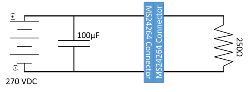
A representative circuit for 270VDC connector tests. Electrical monitoring equipment not shown in circuit.
Physical Configuration
The mated connector was mounted with one side on a moveable platform such that the connector could be drawn out at a constant rate and the other connector was held at a fixed location. During tests, the connector separation speed was fixed and drawn apart until a 5cm connector separation was achieved. Lastly, the connector coupling ring was removed to allow for easier de-mating during the test performance.
Placement of pin
Four tests were performed with two pin-to-pin separation distances between the high voltage pin and the ground voltage pin and two circuit resistances. The four tested configurations are shown in Table 1.
|
Test Configuration |
Circuit Resistance (Ohms) |
Minimum Pin Separation (mm) |
|
1 |
250 |
2.0 |
|
2 |
250 |
7.2 |
|
3 |
100 |
2.0 |
|
4 |
100 |
7.2 |
Example Test
A short video of one test is shown below. The connector was initially mated with the test power on and 1A of current supplied to the test load. The connector was then slowly separated at a speed approximately 1cm/s. The separation movement can be seen as noise on the voltage and current data recorded from the circuit. Once the pins and sockets in the connector were separated, an arcing event was observed first by molten metal leaving the connector followed shortly thereafter by an arc plume emerging from both sides of the connector.
Based on the electrical data, the connector is estimated to have traveled approximately 1mm during the active time of the arcing event.
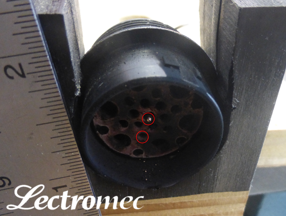
Photo of non-fixed connector after arcing event. The red circles indicate the position of the sockets.
The post-test examination of the connectors showed almost total damage to the installed connector sockets. One of the sockets remains visible at the center and the other socket was no longer visible. Attempts were made to remove the contacts to gather further information on the extent of damage, but neither contact could be extracted.
Electrical Results
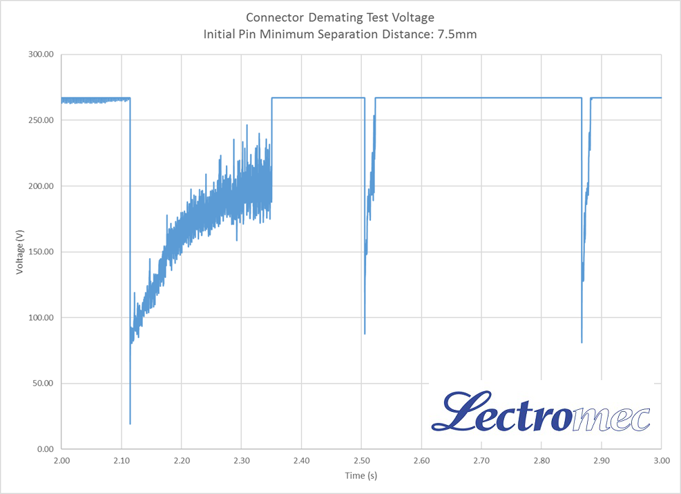
The representative voltage and current traces are shown in the accompanying figures.
In this example, there was a longer event (0.25s) and two brief subsequent events (> 0.03s) within the span of 0.8s; the total active arcing time was 0.3s.
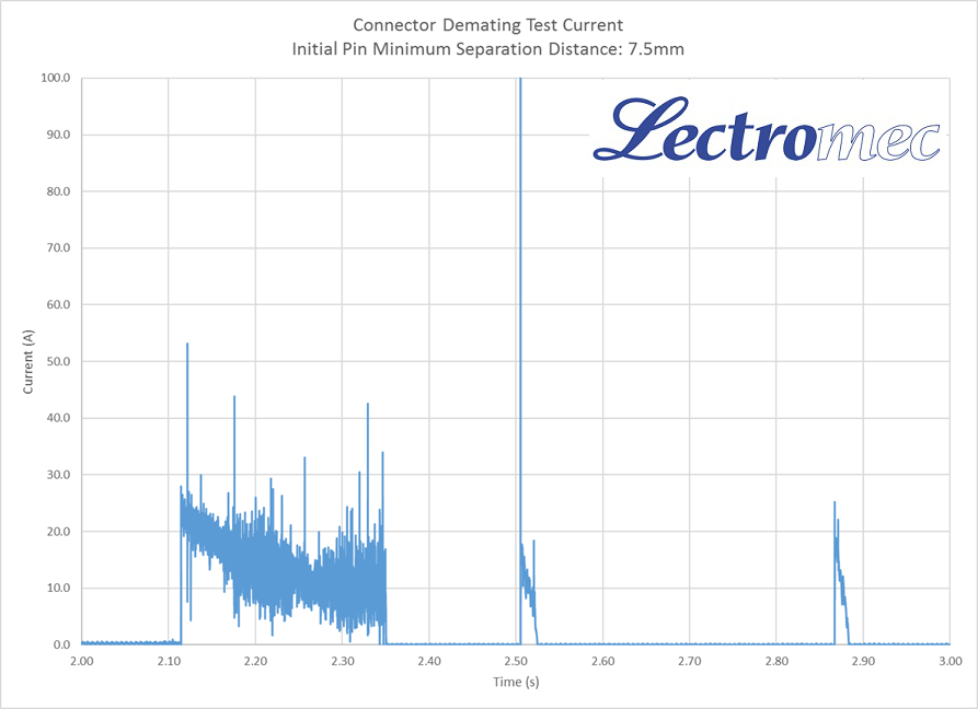
Recorded electrical current from 7.5mm minimum pin-to-pin separation test.
Examination of the current during the longer event showed a downward sloping current. At the start of the event, the current was 21A then decreased to 10A after 0.25s. This corresponded to the increase in circuit voltage over the same interval. The electrical data suggests that an arc was drawn out once the contacts separated quickly and arced between the 270VDC and ground contacts. The damage to the connector contacts and increased separation distance would be a contributing factor for the increasing voltage during the event.
Similar results were seen in each of the other four test configurations. The same voltage and current patterns were seen, as was the damage to the connector contacts.
Conclusions
Failure Impact
Recorded electrical current from 7.5mm minimum pin-to-pin separation test.
The tests performed in this research show the dangers of connector de-mating during circuit operation. Furthermore, the tests showed that the physical separation of 7.2mm was insufficient to prevent arcing between powered and grounded contacts within the connector.
It is expected that, had the connectors been populated with more circuits, it is likely that the event would have lasted longer with more damage.
Had the connector shell been connected to ground, it is unlikely that there would have been a significant change in test results. While the connector shell may have been directly arced to during the event, the limiting factor was the 270VDC contact destruction.
Review of the test data showed that the 270VDC arcing closely resembled similar tests performed with 28VDC power. Although the voltage is 10x greater, this suggests that many of the same analysis techniques used with the 28VDC can be applied to the higher voltage DC systems.
Uncommanded Activation
A concern that emerges from this testing is the potential for commanded circuit activation (Lectromec performed similar research back in 2005) . The tests show that a separation distance of 7.2mm is insufficient to isolated circuits. Cross-circuit activation is commonly addressed as part of bent-pin analyses. Although bent pin analysis conducted in EWIS design reviews examine the possible physical connections made by bent contacts within a connector, it may become necessary that the analyses also consider a greater number of events when examining circuits with 270VDC.
Further research is necessary to determine the impact of separation distance and circuit current to provide better limits on contact-to-contact failure analysis.
Installation and Sustainment
Both installers and maintainers should be aware of the dangers of mishandled connectors. This research shows the dangers of demating active circuits with 270VDC.

Michael Traskos
President, Lectromec
michael.traskos@lectromec.comMichael has been involved in wire degradation and failure assessments for more than a decade. He has worked on dozens of projects assessing the reliability and qualification of EWIS components. Michael is an FAA DER with a delegated authority covering EWIS certification and the chairman of the SAE AE-8A EWIS installation committee.