View Latest Blog Entries
Close
Categories
Testing & Assessment Certification Standard & Regulation Aging Wires & Systems Maintenance & Sustainment Management Conference & Report Protection & Prevention Research Miscellaneous Arcing
Popular Tags
Visual Inspection High Voltage AS50881 MIL-HDBK MIL-HDBK-525 FAR AS4373 Electromagnetic Interference (EMI) Maintenance FAR 25.1707 Wire System Arcing Damage
All Tags in Alphabetical Order
2021 25.1701 25.1703 abrasion AC 33.4-3 AC 43 Accelerated Aging ADMT Aging Systems AIR6808 AIR7502 Aircraft Power System aircraft safety Aircraft Service Life Extension Program (SLEP) altitude arc damage Arc Damage Modeling Tool Arc Fault (AF) Arc Fault Circuit Breaker (AFCB) Arc Track Resistance Arcing Arcing Damage AS22759 AS22759/87 AS23053 AS29606 AS4373 AS4373 Method 704 AS50881 AS5692 AS6019 AS6324 AS81824 AS83519 AS85049 AS85485 AS85485 Wire Standard ASTM B355 ASTM B470 ASTM D150 ASTM D2671 ASTM D8355 ASTM D876 ASTM F2639 ASTM F2696 ASTM F2799 ASTM F3230 ASTM F3309 ATSRAC Attenuation Automated Wire Testing System (AWTS) Automotive Avionics backshell batteries bend radius Bent Pin Analysis Best of Lectromec Best Practice bonding Cable Cable Bend cable testing Carbon Nanotube (CNT) Certification cfr 25.1717 Chafing Chemical Testing Circuit Breaker circuit design Circuit Protection cleaning clearance Coaxial cable cold bend collision comparative analysis Compliance Component Selection Condition Based Maintenance Conductor Conductor Testing conductors conduit Connector Connector rating connector selection connector testing connectors contacts Corona Corrosion Corrosion Preventing Compound (CPC) corrosion prevention Cracking creepage D-sub data analysis data cables degradat Degradation Delamination Derating design safety development diagnostic Dielectric breakdown dielectric constant Dimensional Life disinfectant Distributed Power System DO-160 dry arc dynamic cut through E-CFR electric aircraft Electrical Aircraft Electrical Component Electrical Power Electrical Testing Electrified Vehicles Electromagnetic Interference (EMI) Electromagnetic Vulnerability (EMV) Electrostatic Discharge EMC EMF EN2235 EN3197 EN3475 EN6059 End of Service Life End of Year Energy Storage engines Environmental Environmental Cycling environmental stress ethernet eVTOL EWIS certification EWIS Component EWIS Design EWIS Failure EWIS sustainment EWIS Thermal Management EZAP FAA FAA AC 25.27 FAA AC 25.981-1C FAA Meeting failure conditions Failure Database Failure Modes and Effects Analysis (FMEA) FAQs FAR FAR 25.1703 FAR 25.1707 FAR 25.1709 Fault fault tree Fixturing Flammability fleet reliability Flex Testing fluid exposure Fluid Immersion Forced Hydrolysis fuel system fuel tank ignition Functional Hazard Assessment functional testing Fundamental Articles Fuse Future Tech galvanic corrosion Glycol Gold Gold plating Green Taxiing Grounding hand sanitizer handbook Harness Design harness protection hazard Hazard Analysis health monitoring heat shrink heat shrink tubing high current high Frequency high speed data cable High Voltage High Voltage Degradation HIRF History Hot Stamping Humidity Variation HV connector HV system ICAs IEC 60851 IEC60172 IEEE immersion insertion loss Inspection installation installation safety Instructions for Continued Airworthiness insulating material insulating tape Insulation insulation breakdown insulation resistance insulation testing interchangeability IPC-D-620 ISO 17025 Certified Lab ISO 9000 J1673 Kapton Laser Marking life limit life limited parts Life prediction life projection Lightning lightning protection liquid nitrogen lithium battery lunar Magnet wire maintainability Maintenance Maintenance costs Mandrel mean free path measurement mechanical stress Mechanical Testing MECSIP MIL-C-38999 MIL-C-85485 MIL-DTL-17 MIL-DTL-23053E MIL-DTL-3885G MIL-DTL-38999 MIL-E-25499 MIL-HDBK MIL-HDBK-1646 MIL-HDBK-217 MIL-HDBK-454 MIL-HDBK-516 MIL-HDBK-522 MIL-HDBK-525 MIL-HDBK-683 MIL-STD-1353 MIL-STD-1560 MIL-STD-1798 MIL-STD-464 MIL-T-7928 MIL-T-7928/5 MIL-T-81490 MIL-W-22759/87 MIL-W-5088 MIL–STD–5088 Military 5088 modeling moon MS3320 NASA NEMA27500 Nickel nickel plating No Fault Found OEM off gassing Outgassing Over current Overheating of Wire Harness Parallel Arcing part selection Partial Discharge partial discharge at altitude Performance physical hazard assessment Physical Testing polyamide polyimdie Polyimide-PTFE Power over Ethernet power system Power systems predictive maintenance Presentation Preventative Maintenance Program Probability of Failure Product Quality PTFE pull through Radiation Red Plague Corrosion Reduction of Hazardous Substances (RoHS) regulations relays Reliability Research Resistance Revision C Rewiring Project Risk Assessment S&T Meeting SAE SAE Committee Sanitizing Fluids Secondary Harness Protection separation Separation Requirements Series Arcing Service Life Extension Severe Wind and Moisture-Prone (SWAMP) Severity of Failure shelf life Shield Shielding Shrinkage signal signal cable Silver silver plated wire silver-plating skin depth skin effect Small aircraft smoke Solid State Circuit Breaker Space Certified Wires Splice standards Storage stored energy superconductor supportability Sustainment System Voltage Temperature Rating Temperature Variation Test methods Test Pricing Testing testing standard Thermal Circuit Breaker Thermal Endurance Thermal Index Thermal Runaway Thermal Shock Thermal Testing tin Tin plated conductors tin plating tin solder tin whiskering tin whiskers top 5 Transient Troubleshooting TWA800 UAVs UL94 USAF validation verification video Visual Inspection voltage voltage differential Voltage Tolerance volume resistivity vw-1 wet arc white paper whitelisting Winding wire Wire Ampacity Wire Bend Wire Certification Wire Comparison wire damage wire failure wire performance wire properties Wire System wire testing Wire Verification wiring components work unit code

Understanding unexpected arc track resistance test results

Management

arc track resistance
Standard circuit configuration of arc track resistance test.

Lectromec has been testing wire for the past thirty years. We have seen nearly every conceivable variation of aircraft wire testing. Some tests are straight forward and require little or no additional explanation of the test results; other tests require a fair bit of explanation to understand the test itself and what the results mean. One question that Lectromec frequently gets when clients receive the results of arc track resistance tests is, “Why is it that the higher resistance circuit configurations result in more damaging arcing events (the ones that cause the most damage to other wires in the test harness)?”

Circuit Setup

Text-based descriptions of arc track resistance testing can be confusing. If you would prefer to start with a video presentation, you may want to watch this two-minute video.

arc track resistance
Thermal circuit breakers do not have simple trip curves and are impacted by the operational temperature. The green band shows acceptable operating conditions in ambient temperature, the lines above and below show performance limits in hot and cold operating conditions.

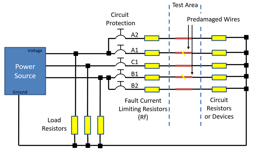
When performing arc resistance tests, the standard practice is that several circuit resistance values are used. In the circuit diagram below, the adjustable resistors (Rf) range from 0.0Ω (no added circuit resistance) to 2.0Ω for a 20AWG wire test. Three tests are performed at each circuit resistance (defined in the particular test standard) and the pass-fail criteria of the test are wire specification specific (see Lectromec’s What do the Results of Arc Track Resistance Testing Mean? article on this.

The minimum test resistance setup (0.0Ω configuration) will yield the highest fault current, and the maximum test resistance setup (2.0Ω configuration) will yield the lowest fault current. It would seem to make sense that a higher current will cause more damage. After all, this would yield the highest electrical power and probably cause the most damage. However, like all things involving Electrical Wire Interconnect Systems (EWIS), everything seems simple until you start getting deep into it.

Stopping the Arcing Event

arc track resistance
Electrical arc energy during arc track resistance test at different circuit resistances.

There are two ways that an arc can stop: the electrical power is removed from the circuit (circuit protection activation) or the distance between the arcing wires is too great and voltage breakdown cannot continue. For the purpose of today’s discussion, we will focus on the circuit protection activation.

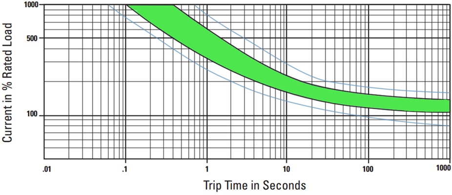
The following figure shows a typical circuit protection trip curve. At high currents, the circuit protection activates very quickly, at lower currents the activation time is much shorter. The green band in the figure shows typical operating temperatures. The outside bands above and below show representative trip times at elevated and sub-zero temperatures respectively.

Example Arcing Event

The following table shows a couple of representative cases for the circuit resistance and total energy in an arcing event. In the case shown here, three assumptions are made:

  1. 0.3Ω of resistance exists between the generated and the test stand (from electrical connections and wiring).
  2. The voltage used in the testing is 208V RMS phase-to-phase.
  3. The circuit protection used in the testing is a 7.5A thermal circuit breaker (as called out for in the test specification).

In the 0.0Ω condition, the total circuit resistance during an arcing event, plus the arc itself, is about 0.85Ω. The RMS current is about 32 times greater than the circuit breaker rating. This is far beyond the typical trip curve shown in the previous figure and can be assumed to cause circuit protection activation after about 0.05seconds or about 20 cycles at 400 Hz (verified by testing). This short event creates a scenario generating about 2500J of arc energy.

In the 2.0Ω condition, the total circuit resistance during an arcing event, plus the arc itself, yields a resistance of 4.85Ω, a roughly five time greater circuit resistance compared to the 0.0 Ω circuit resistance. The RMS current for the 2.0Ω test is about six times greater than the circuit breaker rating – an overcurrent level within the circuit protection specification. The trip time ranges from 0.3 – 0.8 seconds and, for the calculation shown, 0.55 seconds is used. Based on these calculations, the 2.0Ω configuration would generate an arcing event lasting 11 times longer and a total energy of about 4900J. This energy is almost two times greater than in the 0.0Ω configuration.

Summing It Up

The arc track resistance test is among the most complicated test performed on aircraft wires. Every part of the circuit design and wire construction can have an impact on the results. With regard to the test results, the arc resistance tests are more than just voltage times current – the circuit protection has a significant impact. Contact Lectromec to find out more about Lectromec’s arc track resistance testing or any of our lab services.

Michael Traskos

Michael Traskos

President, Lectromec

Michael has been involved in wire degradation and failure assessments for more than a decade. He has worked on dozens of projects assessing the reliability and qualification of EWIS components. In September 2014, Michael was appointed as an FAA DER with a delegated authority covering EWIS certification.