View Latest Blog Entries
Close
Categories
Testing & Assessment Certification Standard & Regulation Aging Wires & Systems Maintenance & Sustainment Management Conference & Report Protection & Prevention Research Miscellaneous Arcing
Popular Tags
Visual Inspection High Voltage AS50881 MIL-HDBK MIL-HDBK-525 FAR AS4373 Electromagnetic Interference (EMI) Maintenance FAR 25.1707 Wire System Arcing Damage
All Tags in Alphabetical Order
2021 25.1701 25.1703 abrasion AC 33.4-3 AC 43 Accelerated Aging ADMT Aging Systems AIR6808 AIR7502 Aircraft Power System aircraft safety Aircraft Service Life Extension Program (SLEP) altitude arc damage Arc Damage Modeling Tool Arc Fault (AF) Arc Fault Circuit Breaker (AFCB) Arc Track Resistance Arcing Arcing Damage AS22759 AS22759/87 AS23053 AS29606 AS4373 AS4373 Method 704 AS50881 AS5692 AS6019 AS6324 AS81824 AS83519 AS85049 AS85485 AS85485 Wire Standard ASTM B355 ASTM B470 ASTM D150 ASTM D2671 ASTM D8355 ASTM D876 ASTM F2639 ASTM F2696 ASTM F2799 ASTM F3230 ASTM F3309 ATSRAC Attenuation Automated Wire Testing System (AWTS) Automotive Avionics backshell batteries bend radius Bent Pin Analysis Best of Lectromec Best Practice bonding Cable Cable Bend cable testing Carbon Nanotube (CNT) Certification cfr 25.1717 Chafing Chemical Testing Circuit Breaker circuit design Circuit Protection cleaning clearance Coaxial cable cold bend collision comparative analysis Compliance Component Selection Condition Based Maintenance Conductor Conductor Testing conductors conduit Connector Connector rating connector selection connector testing connectors contacts Corona Corrosion Corrosion Preventing Compound (CPC) corrosion prevention Cracking creepage D-sub data analysis data cables degradat Degradation Delamination Derating design safety development diagnostic Dielectric breakdown dielectric constant Dimensional Life disinfectant Distributed Power System DO-160 dry arc dynamic cut through E-CFR electric aircraft Electrical Aircraft Electrical Component Electrical Power Electrical Testing Electrified Vehicles Electromagnetic Interference (EMI) Electromagnetic Vulnerability (EMV) Electrostatic Discharge EMC EMF EN2235 EN3197 EN3475 EN6059 End of Service Life End of Year Energy Storage engines Environmental Environmental Cycling environmental stress ethernet eVTOL EWIS certification EWIS Component EWIS Design EWIS Failure EWIS sustainment EWIS Thermal Management EZAP FAA FAA AC 25.27 FAA AC 25.981-1C FAA Meeting failure conditions Failure Database Failure Modes and Effects Analysis (FMEA) FAQs FAR FAR 25.1703 FAR 25.1707 FAR 25.1709 Fault fault tree Fixturing Flammability fleet reliability Flex Testing fluid exposure Fluid Immersion Forced Hydrolysis fuel system fuel tank ignition Functional Hazard Assessment functional testing Fundamental Articles Fuse Future Tech galvanic corrosion Glycol Gold Gold plating Green Taxiing Grounding hand sanitizer handbook Harness Design harness protection hazard Hazard Analysis health monitoring heat shrink heat shrink tubing high current high Frequency high speed data cable High Voltage High Voltage Degradation HIRF History Hot Stamping Humidity Variation HV connector HV system ICAs IEC 60851 IEC60172 IEEE immersion insertion loss Inspection installation installation safety Instructions for Continued Airworthiness insulating material insulating tape Insulation insulation breakdown insulation resistance insulation testing interchangeability IPC-D-620 ISO 17025 Certified Lab ISO 9000 J1673 Kapton Laser Marking life limit life limited parts Life prediction life projection Lightning lightning protection liquid nitrogen lithium battery lunar Magnet wire maintainability Maintenance Maintenance costs Mandrel mean free path measurement mechanical stress Mechanical Testing MECSIP MIL-C-38999 MIL-C-85485 MIL-DTL-17 MIL-DTL-23053E MIL-DTL-3885G MIL-DTL-38999 MIL-E-25499 MIL-HDBK MIL-HDBK-1646 MIL-HDBK-217 MIL-HDBK-454 MIL-HDBK-516 MIL-HDBK-522 MIL-HDBK-525 MIL-HDBK-683 MIL-STD-1353 MIL-STD-1560 MIL-STD-1798 MIL-STD-464 MIL-T-7928 MIL-T-7928/5 MIL-T-81490 MIL-W-22759/87 MIL-W-5088 MIL–STD–5088 Military 5088 modeling moon MS3320 NASA NEMA27500 Nickel nickel plating No Fault Found OEM off gassing Outgassing Over current Overheating of Wire Harness Parallel Arcing part selection Partial Discharge partial discharge at altitude Performance physical hazard assessment Physical Testing polyamide polyimdie Polyimide-PTFE Power over Ethernet power system Power systems predictive maintenance Presentation Preventative Maintenance Program Probability of Failure Product Quality PTFE pull through Radiation Red Plague Corrosion Reduction of Hazardous Substances (RoHS) regulations relays Reliability Research Resistance Revision C Rewiring Project Risk Assessment S&T Meeting SAE SAE Committee Sanitizing Fluids Secondary Harness Protection separation Separation Requirements Series Arcing Service Life Extension Severe Wind and Moisture-Prone (SWAMP) Severity of Failure shelf life Shield Shielding Shrinkage signal signal cable Silver silver plated wire silver-plating skin depth skin effect Small aircraft smoke Solid State Circuit Breaker Space Certified Wires Splice standards Storage stored energy superconductor supportability Sustainment System Voltage Temperature Rating Temperature Variation Test methods Test Pricing Testing testing standard Thermal Circuit Breaker Thermal Endurance Thermal Index Thermal Runaway Thermal Shock Thermal Testing tin Tin plated conductors tin plating tin solder tin whiskering tin whiskers top 5 Transient Troubleshooting TWA800 UAVs UL94 USAF validation verification video Visual Inspection voltage voltage differential Voltage Tolerance volume resistivity vw-1 wet arc white paper whitelisting Winding wire Wire Ampacity Wire Bend Wire Certification Wire Comparison wire damage wire failure wire performance wire properties Wire System wire testing Wire Verification wiring components work unit code

Chemical formulas and structures for wire systems

Management

Elemental abbreviations that may be used for wire systems

C = carbon           H = hydrogen             Cl = chlorine             N = nitrogen             F = fluorine      O = oxygen

Wire System Degradation
Structure I
Wire System Degradation
Structure II
Wire System Degradation
Structure III
Wire System Degradation
Structure IV
Wire System Degradation
Structure V
Wire System Degradation
Structure VI
Wire System Degradation
Structure VII
Wire System Degradation
Structure VIII
Wire System Degradation
Structure IX
Wire System Degradation
Structure X
Wire System Degradation
Structure XI
Wire System Degradation
Structure XII

Understanding wire systems includes the concept of chemical formulas and structures. In fact, it is the basis for a beginning understanding of all materials, and this includes wire systems. Most everyone has heard of chemical formulas, whether they realize it or not-often from the media. For example, H2O is the “shorthand” for a water molecule. The empirical chemical formula often does not give us an indication of how the atoms are bonded (or arranged) in a molecule. A very simple molecule is H2, hydrogen, and it is easy to visualize, i.e., HH. The chemical method for depicting the structure of this molecule is H-H. The line shows the bonding between the two atoms, and it is used to indicate two electrons in the bond. With H2 these are the only electrons for the molecule.

If you are interested in wire systems, you may want to read Lectromec’s 7 Tenets of Wire System Installation article.

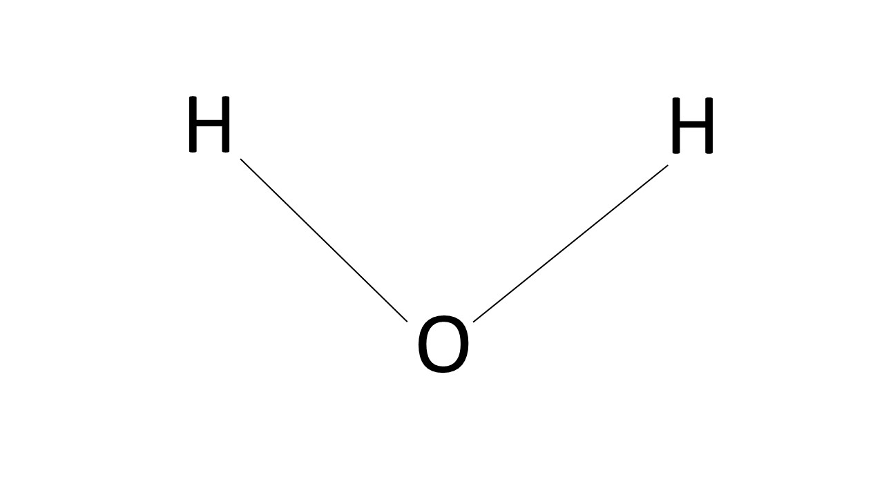
If we have three atoms, there are more atomic and spatial arrangements possible. It is conceivable to write CO2 (carbon dioxide) as COO or OCO as the atomic arrangement. In fact, OCO is the correct configuration. The correct bond designation for CO2 is O=C=O. Again, each line indicates two electrons from the outer shells of these atoms; the two lines between the carbon atom and an oxygen atom are called a double bond. Four of the electrons are from the carbon atom and each oxygen atom supplies two electrons. (Note: for neutral species there should be four bonds to each carbon atom.) This representation also indicates that CO2 is linear; this is the normal structure. For another three atom molecule, H2O, the structure H-O-H shows the correct number of bonds, but not the proper spatial configuration. For water this is (Structure I) with the HOH angle being just under 110o. The structure I is a visual description of the atomic bonding and spatial orientation for water. Depending on the context, either the simple linear representation or the spatial representation is used. More complex molecules will follow a similar approach.

Simple Organic Molecules that may be pat of aerospace wire systems

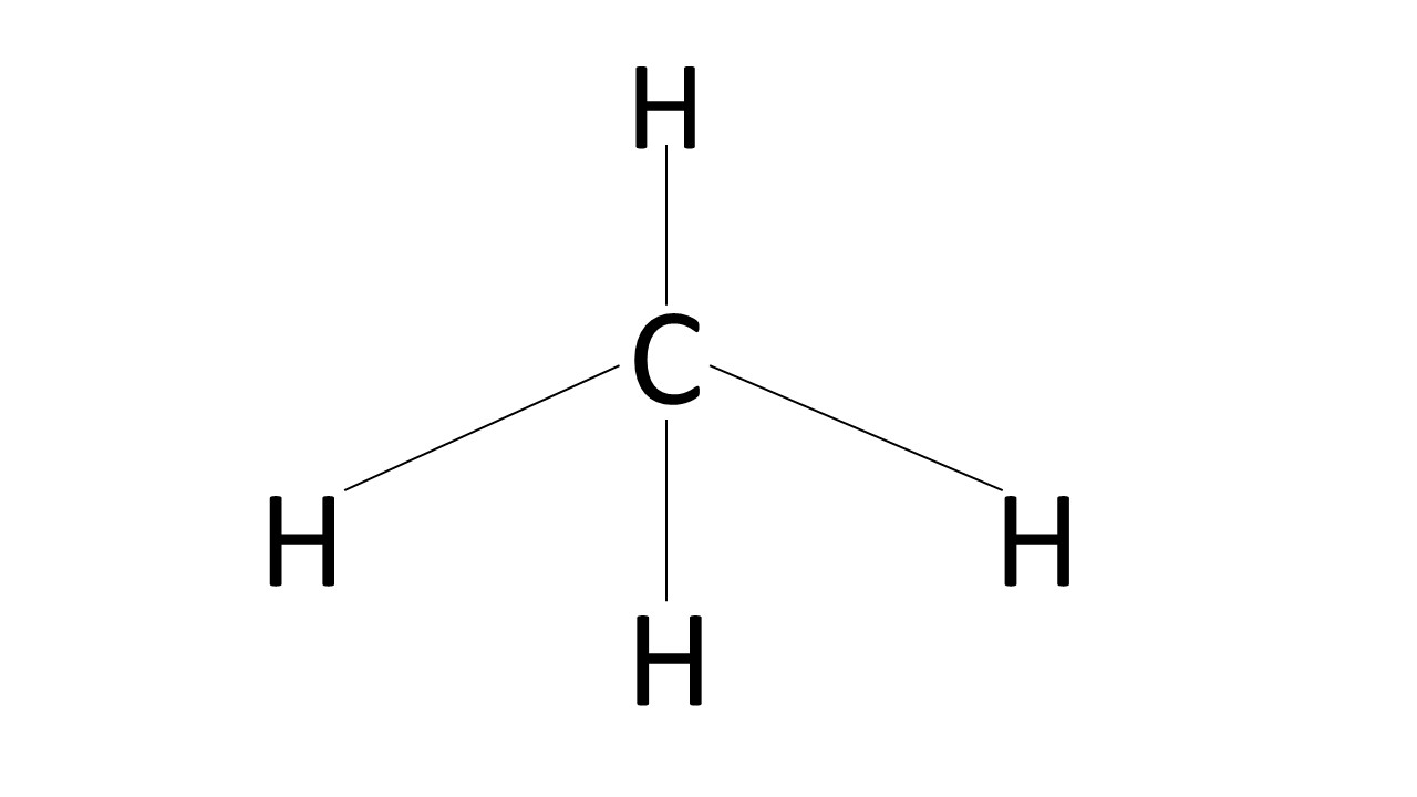
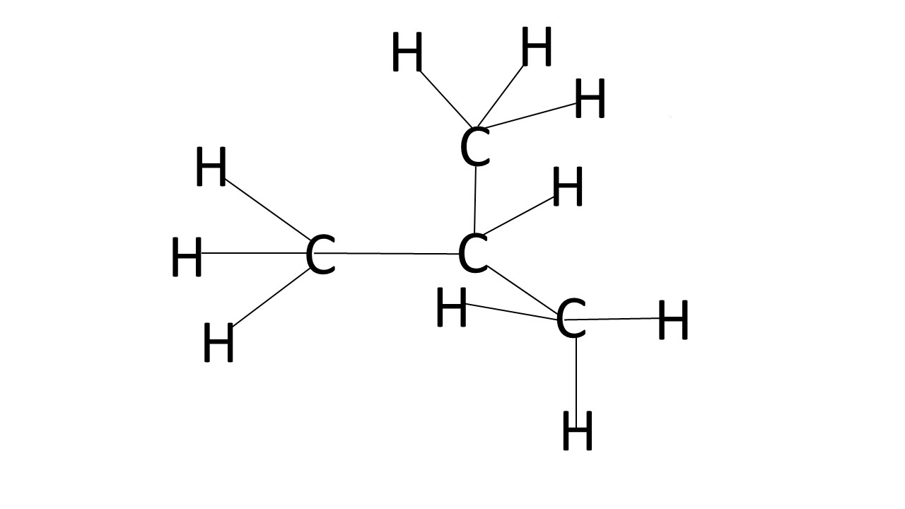
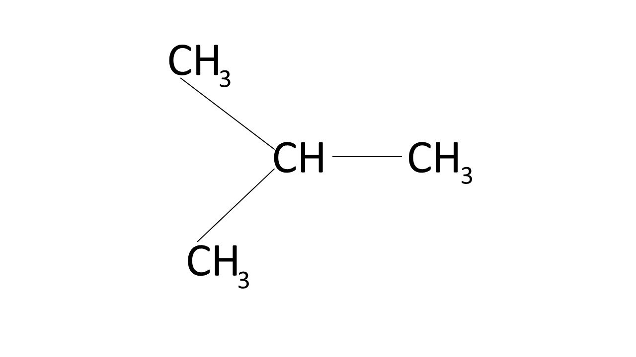
Carbon is the basis of organic chemicals and the following summary is sufficient for the materials encountered at Lectromec. (Note: there are some completely inorganic molecules and ions that contain carbon; but, the number is relatively small). Perhaps the simplest organic carbon molecule is methane, CH4, the main component in natural gas. The structural formula for CH4 is (Structure II) where again each line represents two electrons. The carbon atom is at the center of a tetrahedron. Going to a higher compound of this series, iso-butane (i-C4H10), the structural formula is more complex as shown in structure III. With these examples it is easy to see that with most organic compounds it is difficult to represent completely a three dimensional structure in two dimensions, since most of them have more than just a few atoms.

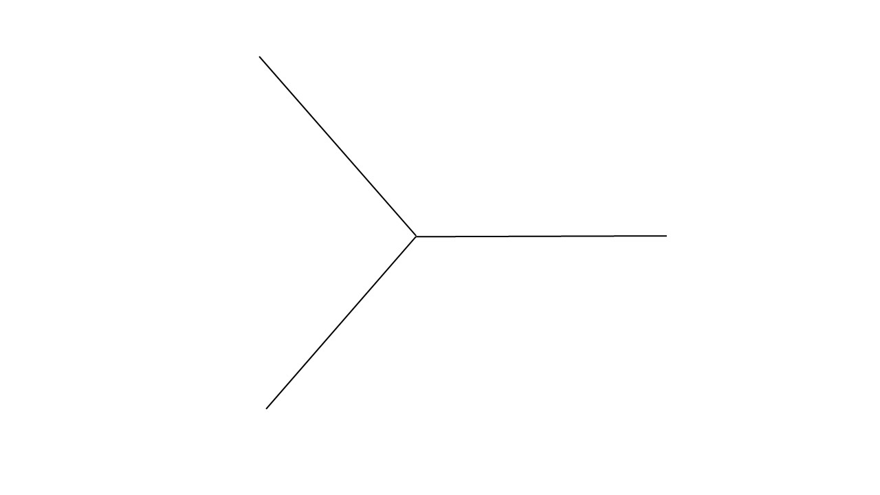
Often this is not tried. The large number of hydrogen atoms makes complete figures very complex when there are more than a few central carbon atoms. There are two ways to overcome this problem. The first is to just indicate the bonds between the carbon atoms, as shown in structure IV for iso-butane.

If there are atoms other than carbon or hydrogen, e.g., oxygen, nitrogen, etc., they will be shown in the structure even if hydrogen and carbon are not. The second approach is not to show the carbon-hydrogen bonds; see structure V for iso-butane.

The organic compounds used as examples above are hydrocarbons, i.e., they contain only carbon and hydrogen. They also are in the class of compounds called aliphatics.

Aromatic Molecules

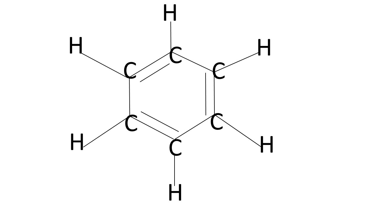
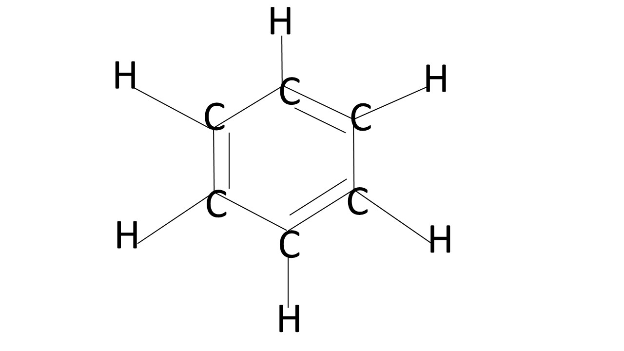
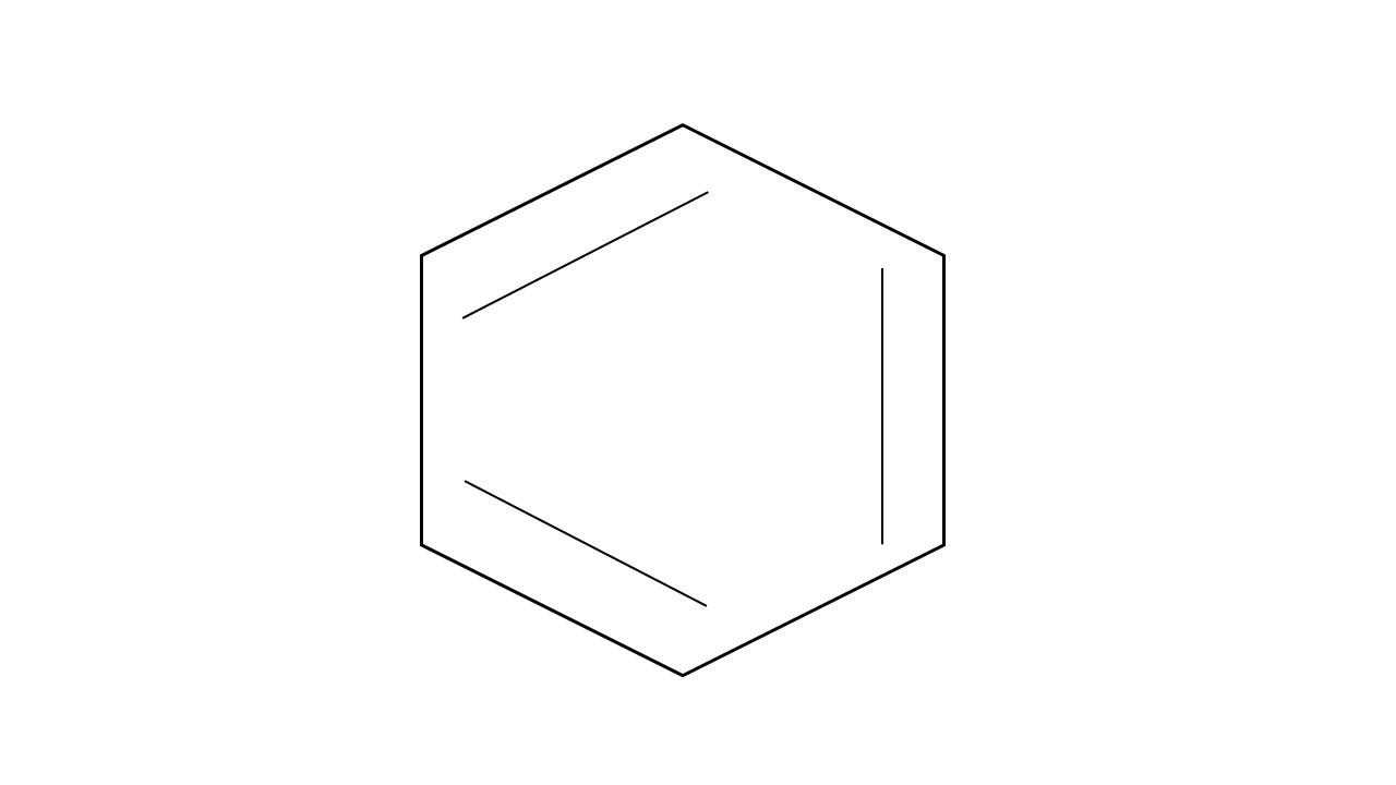
The other major category for organic molecules is aromatic and is based on benzene. The structural formula for benzene is (see Structure VI), but it is equally correct to draw the benzene molecule in this fashion (as in Structure VII).

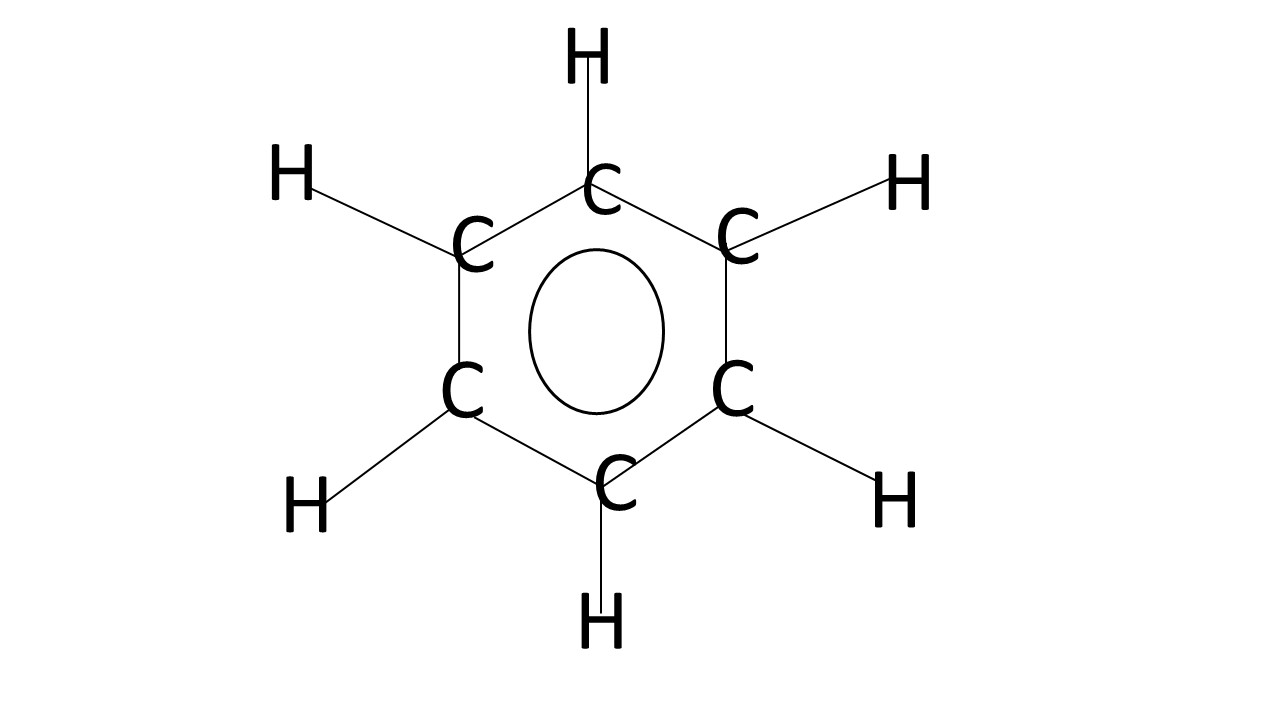
These structures (VI and VII) are the same, since a simple rotation can change one representation to the other. (Actually, they are in resonance with each other; a more realistic representation is shown in structure VIII where we are going between structures VI and VII.)

Again when depicting benzene based molecules, often the structural formula will omit the carbon-hydrogen bonds, and in some instances the carbon and hydrogen atoms are omitted as shown in IX.

Polymers

The word Polymer comes from the Greek “poly” meaning many, and “meros”, parts or units.

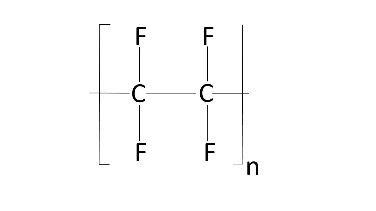
With polymers the same conventions are used for structural formulas. For example, Poly (tetrafluorethylene) (the duPont trade name for this material is Teflon® and often abbreviated as PTFE) is shown in structure X.

Since a polymer is just the repeat of a simple molecule, the structural formula follows the same conventions with the brackets enclosing the representation of the basic molecular unit. This is not an exact spatial representation, but it requires less space. Another structural representation for this polymer is [CF2-CF2]n. As with the hydrocarbon examples, the carbon-fluorine bonds are omitted. “n” will range from under ten to thousands depending on the polymer.

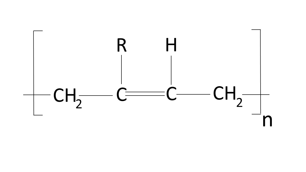
In some instances the letter R is used. This indicates that many different groups of atoms or an element can be bound to the other atom, and is used to show a class of polymers or compounds. An example is shown in structure XI.

Polymer Naming

A brief overview about polymer naming is in the Chemical Names page.
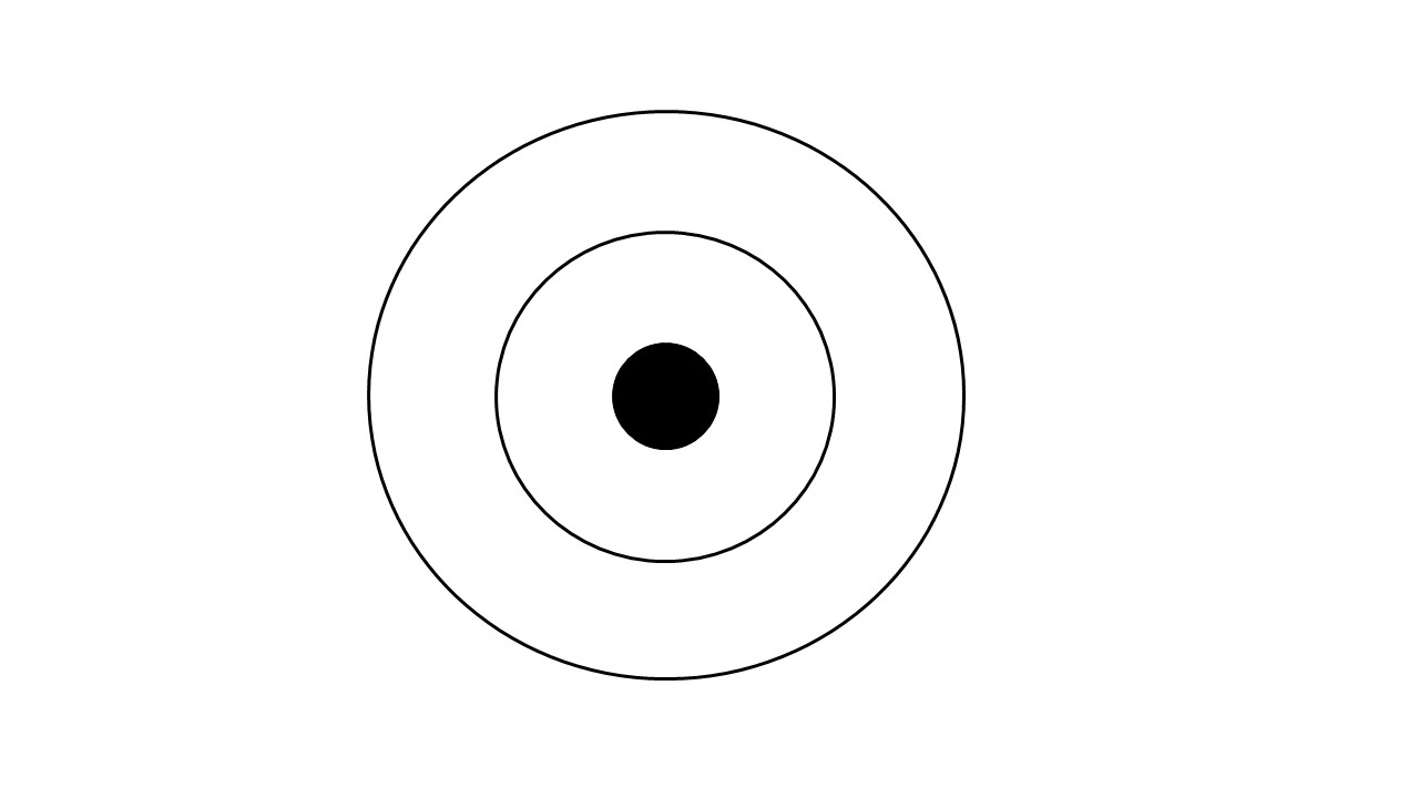
Atomic Structure

This is a very brief description of atomic structure that is not completely correct, but will serve to give a simple picture. The two main stable components of an atom are the nucleus (composed of protons and neutrons) and the orbiting electrons. The structure of an element is a “solar system” (XII) with the electrons orbiting the central nucleus. Each element has a set number of electrons and protons. The electrons that have discussed above are at the very edge of the “solar system” and are known as valence electrons.

Michael Traskos

This article was written by the Lectromec technical team. Aircraft wiring is our passion and we strive to make a contribution to the field by sharing our expertise through blogs, podcasts, and videos. We hope you find this information helpful. We also encourage you to submit comments and spur discussions.