
Connector Contact Resistance: Why Milliohms Matter
A connector may contain dozens or hundreds of electrical contacts, but each circuit still depends on a very small physical interface between two mating surfaces. When that interface is clean, properly aligned, and held together with sufficient force, its resistance is typically measured in milliohms. When the interface deteriorates, that small value can become a significant reliability problem.
The contact resistance connector test provides a measure of the interface quality. The test is used to support qualification, product comparison, initial inspection, failure investigation, and aging assessments. The test itself is mostly straightforward, and obtaining a numerical result is not a challenge. The challenge is determining whether the result represents the contact, whether performance of the measurement altered the interface, and whether the result is acceptable for the intended application. This article reviews the basic factors that impact performance and the failure consequences if contact resistance is not controlled.
What Is Contact Resistance?
Electrical current does not pass uniformly across the full mated area of a contact. Instead, it travels through a much smaller collection of microscopic conducting points. The measured resistance includes the constriction of current through these points and any additional resistance created by oxide films, corrosion products, contamination, or wear debris.
Connector requirements may express this performance as resistance in milliohms or as voltage drop at a specified current. These are two ways of describing the same behavior. For example, a contact with a 55-millivolt drop at 7.5 amperes has a resistance of approximately 7.3 milliohms.
It is also important to define the measurement boundary. A contact-only test isolates the mated interface as much as is practical. A harness-path measurement may include the contacts, crimps, wires, splices, and test-adapter interfaces. Both measurements can be useful, but they answer different questions and should not be compared as though they are equivalent.
Why a Few Milliohms Matter
In a power circuit, contact heating follows the relationship P = I2R. As current increases, even a small resistance change can generate excess heat inside a tightly packed connector. Consider a contact carrying 7.5 amperes; at 7.3 milliohms, the contact dissipates about 0.41 watts. If degradation raises the resistance to 15 milliohms, the dissipation increases to about 0.84 watts. The change may appear small on a resistance meter, but the resulting temperature rise can accelerate oxidation, weaken nearby materials, and further increase resistance. This creates a feedback loop that can eventually lead to overheating or loss of continuity.
Low-level signal contacts present a different problem. Their currents may be too small to generate significant heating, but an oxide film or intermittent interface can distort or interrupt the signal. A conventional continuity check may still show a closed circuit even though the connector cannot reliably support its intended function. Demating and remating a connector can help because compression on the contact “wipes” the surface, breaking the oxide layer and showing a lower resistance. In effect, there is a reason for “unplug it and plug it back in.”
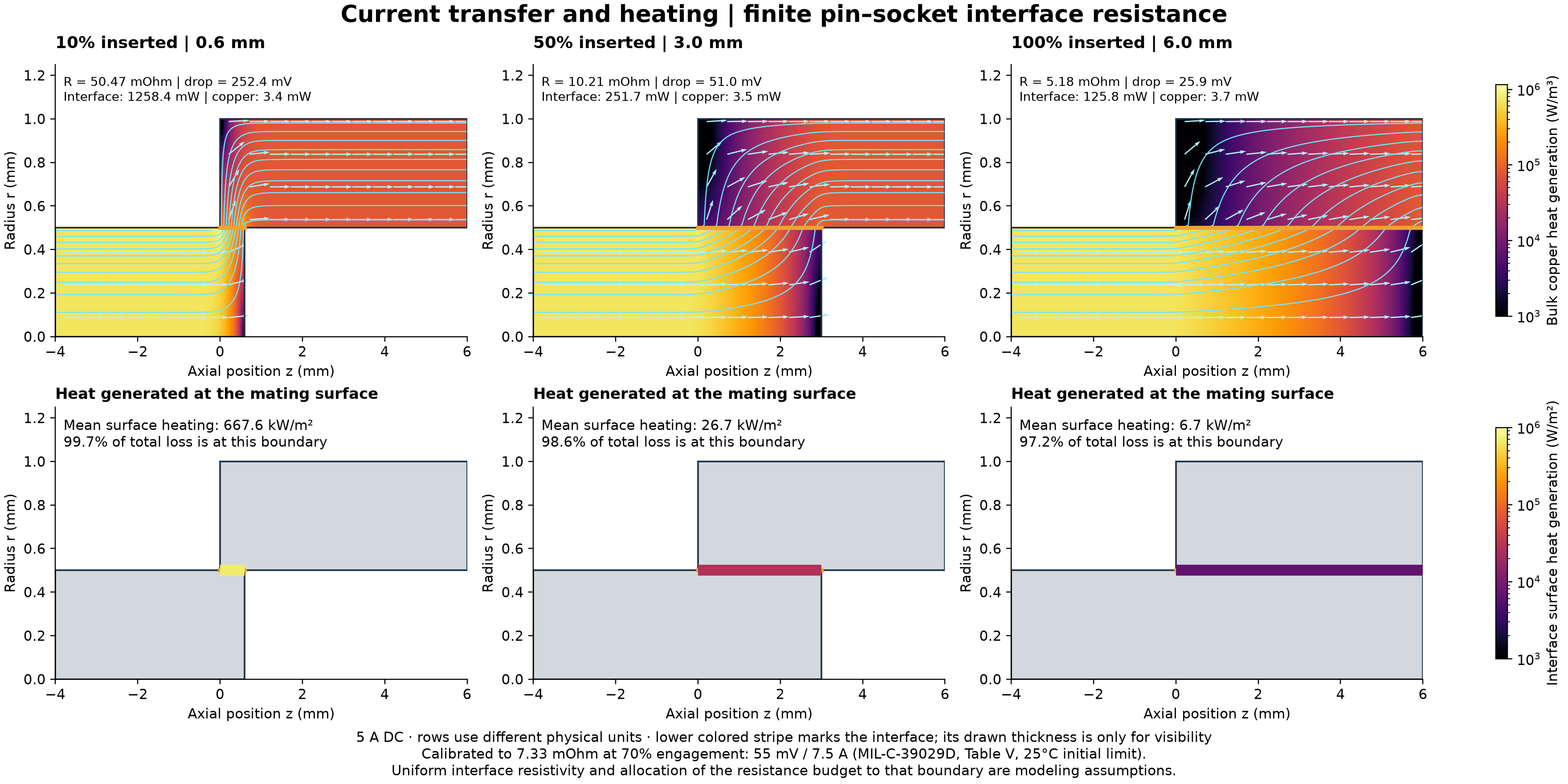
The following figure helps demonstrate this concept from the perspective of contact placement. This simplified two-dimensional model conveys how contact engagement can impact heating and resistance values. If a contact is only 10% inserted, the area for current transfer between the pin and socket narrows significantly. As the contact engagement area increases, the field lines expand, there is more surface area for energy transfer, and the voltage drop decreases.
What Causes Contact Resistance to Change?
Contact resistance is affected by the complete contact system, not just the conductivity of the base metal. Important factors include:
- Plating and base material: Gold, silver, tin, and nickel systems have different conductivity, oxidation, wear, and temperature characteristics.
- Contact geometry and force: Contact beams, spring force, wipe, and alignment determine the size and stability of the conducting interface.
- Contamination: Dust, processing residue, fluids, and foreign material can separate mating surfaces or create resistive films.
- Fretting and vibration: Small repeated movements can wear through plating and generate oxidized debris at the interface.
- Corrosion: Moisture, salt, and dissimilar-metal combinations can reduce the effective conducting area.
- Mating cycles: Repeated engagement and separation can remove surface films, but they can also wear plating and reduce long-term stability.
- Temperature: Thermal expansion, stress relaxation, and self-heating can change contact force and accelerate degradation.
Because these mechanisms interact, a static resistance measurement taken before environmental testing provides only a baseline. In product qualification programs, such as for AS39029-style contacts, the contact resistance measurement is typically repeated after vibration, shock, humidity, salt fog, temperature cycling, durability, or other conditioning to determine whether the interface remains stable. Similar to the way dielectric voltage withstand testing is a common post-exposure test for wires and cables, contact resistance measurements determine if the connector sample passes or fails.
Measuring Milliohm-Level Resistance
For static connector measurements, a four-wire Kelvin configuration is generally preferred. Two leads supply the test current and two separate leads measure voltage across the contact. This prevents most lead and fixture resistance from being added directly to the reported value. This distinction is important because ordinary test leads can have resistance comparable to, or greater than, the contact under evaluation. A two-wire handheld multimeter is a great tool for identifying an open circuit, but it is usually not suitable for characterizing milliohm-level contact performance where the measurement accuracy must be at least two orders of magnitude better.
Low-voltage measurements are also sensitive to thermal electromotive forces created by dissimilar metals and temperature gradients. Current reversal, offset compensation, stable fixturing, short sense leads, and controlled current dwell times can reduce these errors. When these tests are performed, it is appropriate that the applied current and voltage be recorded, as well as the measurement points, stabilization period, equipment accuracy, and environmental conditions. While this might seem like overkill, each of these factors, if not controlled, can create the need for significant rework when used as part of production-line testing or first-article inspections.
The test fixture design deserves particular attention during setup and control. Probing into a connector can damage a contact, spread a socket, or produce inconsistent contact points. Representative mating interfaces or controlled measurement gauges provide better repeatability and reduce the risk that the test itself changes the specimen. The gauges should be verified and protected from inadvertent damage when not in use.
Dry-Circuit Versus Loaded Testing
When testing a contact, the measurement energy must match the intended question. Low-level contact resistance (LLCR), commonly called dry-circuit testing, uses limited voltage and current so the measurement does not electrically puncture a surface film. This is especially critical when evaluating contacts used for low-energy signals. A higher test current can break through an oxide layer and produce an artificially low reading; the contact may appear acceptable during the test even though the actual signal circuit does not have enough energy to overcome the same film in service.
Power contacts, on the other hand, are commonly evaluated using a specified current or millivolt-drop method. For these types of contacts, the current selection and dwell time matter. Excessive current or a long dwell can heat the specimen, alter the resistance, and turn the measurement into an unintended thermal test. The current must be high enough to produce a good reading, but low enough that the resistance does not change because of heating.
When contact resistance is part of dynamic testing, another approach is usually employed. A bench resistance meter may capture a stable value before and after vibration but completely miss microsecond interruptions that occur only while the connector is moving. When momentary discontinuity is a concern, the test setup needs an event detector or high-speed acquisition system capable of monitoring the contact during vibration or shock. A microsecond circuit interruption may not sound like much until a 500 MHz signal loses 500 bits.
Standards and Acceptance Criteria
EIA-364 and IEC 60512 contain widely used methods for connector contact-resistance and contact-disturbance testing. Aerospace connector and contact specifications that include the MIL-DTL connector families and SAE AS39029 detail specifications apply these test methods. An important factor to note is that the test method explains how to make the measurement but does not establish one universal resistance limit for every connector. The governing product specification, detail sheet, qualification plan, or approved test procedure must define the current, measurement points, number of samples, conditioning sequence, and allowable result.
Interpreting the Results
When evaluating the performance of a contact and the associated contact resistance, the average resistance alone can hide a problem. A useful evaluation should consider the initial value, change from baseline, worst-performing contact, variation across the sample population, and any intermittent events observed during dynamic testing.
When a steadily increasing value is observed, the degradation mechanisms identified earlier should be narrowed down based on the type of contact, when it is observed, and information from visual inspection. A resistance value that increases during vibration and returns to the initial value afterward suggests an unstable interface that a static inspection would likely miss. One outlying contact in a large connector may also be more important than a favorable overall average because each position supports a separate circuit function.
Test results should therefore be reviewed in the context of circuit current, signal sensitivity, installation environment, failure consequences, and maintenance expectations. The objective is not simply to produce a low number. It is to demonstrate that the contact interface remains electrically stable under the conditions it will experience in service.
Conclusion
Contact resistance is one of the clearest indicators of connector-interface condition, but only when it is measured correctly and interpreted within the applicable requirements. Proper fixturing, appropriate test energy, controlled measurement boundaries, and post-conditioning comparisons turn a milliohm reading into useful engineering evidence.