Key Takeaways
- Wire harness ampacity (the maximum amount of current a wire harness can transfer without overheating) must be part of wire harness design.
- Secondary wire harness protection materials are needed and they are a critical part of the EWIS
- There is a thermal cost with the use of secondary wire harness protection.
If you are standing outside on a cold winter day, would you be warmer in a T-shirt or in a jacket? The answer is obvious, but somehow that ‘obvious answer’ is obscured when thinking of aircraft wire harness design. A common question of OEMs and aftermarket modifiers is: how much of an impact (if any) does secondary harness protection have on wire harness heating?
Lectromec took time this last week to put together a representative harness and run tests to generate data on the thermal impact of three secondary wire harness protection schemes. While this data is not representative of every wire harness configuration, it does provide a basis for determining if additional testing (or simulation) are needed for your application.
Background
As electrical energy is transmitted down a wire, there is inherent resistance of the current carrier. This resistance leads to the wire/cable heating. With more current, the heating is more pronounced, and at some current level, the heating can exceed the temperature rating of the conductor and/or insulation.
For those interested in learning more about these ideas, Lectromec has several articles on the topic:
To take this idea one step further, not all wire harnesses are the same and depending on the function, location, and/or separation needs, some wire harnesses (or sections of wire harness) will need additional protection. Sometimes this protection is needed for physical protection (think chafe protection) or for electrical protection (think shielding for EMI). How this secondary protection impacts the temperature rise of a harness was the objective of these tests.
Test Setup
The test was setup with the following parameters:
- 10x 20AWG (2ft harnesses) wires attached to a circuit set to carry 12A when at the ambient temperature of 23oC. As the wires heated, the current decreased as the conductor resistance increased. While this current level is over the typical rated current for the 20AWG wires (20AWG is typically coupled with a 7.5A circuit protection), it simply represents a system running warm.
- The wires used were of wire specification AS22759/34 (tin plated copper conductor with XL-ETFE insulation).
- One open and three secondary wire harness protection techniques were evaluated:
- Open harness
- Nomex protected (Similar to EN6049-006 products)
- Shielded harnesses (no other protection)
- Shielded with Nomex on top
Thermal measurement was captured on the outside of one wire at the center of the wire harness. While it is typically recommended that the temperature is captured on the conductor, we chose to measure the temperature on the outside surface of one wire for expediency.
What Should be Expected?
Starting with the theoretical basis is always a good idea. Harness derating has been covered in past articles and this article will not delve into it (see list of articles above). Running the numbers through the AS50881 derating suggests that a single wire would have a temperature increase of about 40oC. With more wires thrown into the wire harness, there is a 50% derating factor and would place the temperature increase around 80oC. This temperature increase is the estimated temperature increase of the open harness wire conductor temperature; the measurement of the insulation temperature will be below this temperature increase.
Testing
Four different wire harness protection schemes were tested. The question: what would be the thermal impact of the testing?
The accompanying photos show the setup. Each harness was hooked up to the circuit in the same way in an open space and secured at both ends allowing the center of the harness to hang freely. The test power was applied, and the sample was left without interference for 15 minutes. The objective was to achieve equilibrium and the first test found equilibrium was achieved in less than 15 minutes. While at least one test was still trending upwards after 15 minutes, the comparison between the secondary protection types is still valid.
The graph below shows the impact:
- Nomex protected: +50oC impact
- Shielded harnesses (no other protection): +10oC impact
- Shielded with Nomex on top: +30oC impact
The potential for the Nomex harness having the largest temperature increase may be due to the limited direct contact points between the wiring harness and the sleeving. In other words, the transfer of thermal energy from the wiring harness to the secondary harness protection was convection and radiation and only limited conduction. The shielded secondary harness protection does act as a good thermal conductor but appears to have the smallest thermal impact.
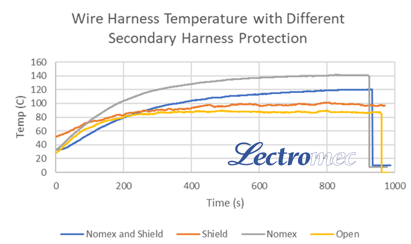
Impact of secondary harness protection on wire harness temperatures.
Knowing the temperature differential between the insulation temperature and conductor temperature, it is likely that the conductor far exceeded the 150C limitation of tin-plated wires. Long-term, this would likely result in degradation of the conductor and intermetallic growth.
Conclusion
The data presented here is not meant to dissuade anyone from using secondary protection if it is needed for their application; Secondary harness protection is a part of aircraft EWIS design. The intent is to provide data to enlighten users that there is an impact on the harness temperature.
The thermal impact of secondary wire harness protection is measurable and can be significant. The thermal conductivity and contact interface with the wire bundle will determine the thermal impact.
If you are looking for data on your wire harness configuration, contact Lectromec. We have the knowledge, experience, and lab capabilities to perform the tests you need.

Michael Traskos
President, Lectromec
michael.traskos@lectromec.comMichael has been involved in wire degradation and failure assessments for more than a decade. He has worked on dozens of projects assessing the reliability and qualification of EWIS components. Michael is an FAA DER with a delegated authority covering EWIS certification and the chairman of the SAE AE-8A EWIS installation committee.