Standardized products made by different manufacturers through different processes will undoubtedly yield variable product performance. The expectation is that each ‘qualified’ product should perform comparatively well, but anecdotal evidence suggests that this is not the case. This paper reviews recent work performed by Lectromec investigating the qualified wire/cable performance variability in both qualification tests as well as custom tests designed to evaluate performance at their maximum defined thresholds.
OEM Expectations
In a survey of OEM EWIS engineers performed by Lectromec, 37% identified that a repeatable quality product was among their top priorities when selecting a wire/cable vendor. This result should not be surprising when considering the miles of wire installed on aircraft and the difficultly to trace down a wire/cable quality issue after the product has been installed.
Perhaps part of the reason one out of every three OEM EWIS engineers identified repeatable quality as a top priority is that, over the last couple of decades, as more companies have entered the field of aerospace wire and cable producers, the variability of product quality has also increased. This result, coupled with the fact that much of the wire harness production is now executed by tier 1 suppliers, OEM EWIS engineers and quality assurance are further separated from the validation and verification processes for which they were once responsible.
The impact of not achieving repeatable quality is certainly a contributing factor as to why many wire harness fabricators and OEMs are experiencing a wide range of EWIS related issues ranging from poor conductor quality (conductor plating issues, corrosion, etc.), insulation defects (insulation breaches, poor sintering, etc.), and poor cable performance (attenuation, shield performance). While some of this is due to poor or aggressive handling of the wiring by installers, the original wire/cable quality is a contributing factor.
When poor quality wire/cables are installed, a new burden is placed on engineering to identify the risk and determine if significant rework including removal of already installed wire harnesses is required or if a mitigation strategy can be implemented. Unfortunately, the costs associated with substandard wire/cable are hard to quantify but have impacted every OEM Lectromec has contacted.
Quantifying Performance
To quantify the performance variances of off-the-shelf wiring, Lectromec procured several wire spools from a reputable aerospace wire and cable distributor (this was done to mitigate the potential for counterfeit parts). In particular, the work focused on those wires on the NavAir Qualified Products List (QPL). As these wires are very common and often have several qualified suppliers, Lectromec believed that this would provide a good representation of those products on the market and from suppliers interested in producing quality products.
When these products were supplied to Lectromec, their identification was removed and assigned a unique identifier such that the test performer was not aware of the product they were testing.
Selection of Wires for Testing
The wire types selected for testing included the AS22759/34 and AS22759/87. The reason for selecting these wire constructions for evaluation was:
- These wire specifications are produced by multiple suppliers. This allowed for testing to be performed on products made from several manufacturers and allowed for generating more data for evaluation.
- These wire types are common on modern aircraft design. While the AS22759/34 design is decades old, it is still a commonly used wire insulation type on a wide variety of platforms. The AS22759/87 wire construction is more commonly used on military platforms and high temperature areas of aircraft.
- Lastly, these are well-established product standards and product types that the variability of first production runs should have been rectified by this point in the product development process.
Selection of Tests
There are dozens of tests that are available and standardized for wire/cable evaluation. From a practical perspective, many of these are not as viable when looking to find performance variances between different wire producers. As a basis for selecting the tests, Lectromec sought to select tests that were:
- Common wire/cable tests frequently used in product evaluation,
- Part of the product specification test requirements (i.e. could that test method be found on the slash sheets requirements),
- Yield a value and not just a pass/fail, and
- Relate to a common problem found as part of installation/operation.
Common Wire Tests
The primary documents used for selecting wire tests are the AS4373, the NEMA 27500, and the ASTM D3032. Tests found in these documents contain the bulk of the wire tests that are used both as part of wire qualification, and OEM selection. Given that testing performed here focuses only on single wires and not cables, signal performance and other signal related evaluations of the cables were not included in the evaluation. For the evaluation conducted here, the 70 tests outlined in the AS4373 were considered.
Product Specification
Of the tests that are outlined in the AS4373, about 50% of these are typically used as part of wire evaluation. Those tests that are not included in the individual slash sheets of the wires were ranked lower in Lectromec’s comparative test selection.
Pass/Fail
Many of the tests only consider pass/fail performance requirements. For example, the forced hydrolysis test requires the samples to be wrapped around a mandrel and submerged in 95°C fluid for an extended duration. At the completion of this test, the samples undergo a wet dielectric test to determine if there has been any breach of the insulation.
These types of tests were removed from the potential test for evaluation because a simple pass/fail result does not provide much information for direct comparison between multiple samples. Tests with a numerical result requiring several trials to provide information on the average and standard deviation were selected.
Common Problems
The test selection criteria objective was to focus on those tests that mimic typical failure modes for wire and cables on aircraft. Based on data Lectromec was able to gather from evaluation of the FAA’s service difficulty reporting database of reported maintenance actions related to EWIS components in 2016, the primary random failure modes for wire and cable are physical damage caused by either pinching or abrasion. These findings aligned with the results published by NavAir after the review of two decades of EWIS failure events.
Selected Tests
Using the criteria defined in earlier, Lectromec reviewed the tests outlined in the AS4373 and the results of this evaluation are shown in the following table.
|
Test Method |
Test Title |
Common Test Method |
Part of Product Specification AS22759/34 |
Part of Product Specification AS22759/87 |
Non-Boolean Result |
Common Install/Op Problem |
|
101 |
Concentricity and Wall Thickness |
x |
x |
x |
x |
|
|
102 |
Insulation Bonding to Potting Compounds |
x |
||||
|
103 |
Insulation Pull-off Force |
x |
x |
x |
x |
|
|
104 |
Insulation Shrinkage/Expansion |
x |
x |
x |
x |
|
|
105 |
Solderability |
x |
x |
|||
|
106 |
Thermal/Mechanical Resistance – Single Wire |
|||||
|
107 |
Thermal/Mechanical Resistance – Bundle |
|||||
|
108 |
Solder Pot Test for Insulation Shrinkage |
|||||
|
109 |
Percent Overlap of Insulating Tapes |
x |
x |
x |
||
|
110 |
Outer Layer Insulation Smoothness |
x |
x |
|||
|
301 |
Needle Abrasion Test |
x |
x |
x |
||
|
401 |
Conductor Diameter |
x |
x |
x |
||
|
402 |
Conductor Elongation and Tensile Breaking Strength |
x |
x |
x |
x |
|
|
403 |
Conductor Resistance |
x |
x |
x |
x |
|
|
404 |
Conductor Strand Blocking |
x |
x |
|||
|
405 |
Adhesion of Nickel Coating |
|||||
|
501 |
Dielectric Constant |
x |
||||
|
502 |
Corona Inception and Extinction Voltages |
x |
||||
|
503 |
Impulse Dielectric |
|||||
|
504 |
Insulation Resistance |
x |
x |
x |
x |
|
|
505 |
Spark Test of Finished Wire Insulation |
x |
||||
|
506 |
Surface Resistance |
x |
x |
x |
||
|
507 |
Time/Current to Smoke |
x |
||||
|
508 |
Dry Arc Propagation Resistance |
x |
x |
x |
||
|
509 |
Wet Arc Propagation Resistance |
x |
x |
x |
||
|
510 |
Voltage Withstand (Wet Dielectric) |
x |
x |
x |
||
|
511 |
Wire Fusing Time |
x |
||||
|
512 |
Voltage Rating |
|||||
|
513 |
Smoke Resistance |
x |
x |
x |
||
|
601 |
Fluid Immersion |
x |
x |
x |
||
|
602 |
Forced Hydrolysis |
x |
x |
|||
|
603 |
Humidity Resistance |
x |
x |
x |
||
|
604 |
Weight Loss Under Temperature and Vacuum |
|||||
|
605 |
Propellant Resistance |
|||||
|
606 |
Weathering Resistance |
|||||
|
607 |
Wicking |
x |
x |
|||
|
608 |
Fluoride Offgassing |
|||||
|
609 |
Nitric Acid Immersion |
|||||
|
701 |
Abrasion |
|||||
|
702 |
Cold Bend |
x |
x |
x |
||
|
703 |
Dynamic Cut Through |
x |
x |
x |
x |
|
|
704 |
Flex Life |
x |
x |
|||
|
705 |
Insulation Tensile Strength and Elongation |
x |
x |
x |
x |
|
|
706 |
Notch Propagation |
x |
x |
|||
|
707 |
Stiffness and Springback |
x |
x |
|||
|
708 |
Mandrel and Wrapback Test |
x |
x |
x |
||
|
709 |
Wrinkle Test |
|||||
|
710 |
Durability of Wire Manufacturer’s Color/Identification |
x |
x |
x |
||
|
711 |
Durability of Wire Installer’s Identification |
|||||
|
712 |
Bend Test |
x |
x |
x |
||
|
713 |
Circumferential Insulation Elongation |
|||||
|
714 |
Wrap, (Mandrel Wrap) |
x |
||||
|
801 |
Flammability |
x |
x |
x |
||
|
802 |
High Pressure/High Temperature Air Impingement (Burst Duct) |
|||||
|
803 |
Smoke Quantity |
x |
||||
|
804 |
Relative Thermal Life and Temperature Index |
x |
x |
x |
||
|
805 |
Thermal Shock Resistance |
x |
x |
x |
||
|
806 |
Property Retention After Thermal Aging |
|||||
|
807 |
Multi-day Heat Aging Test (Life Cycle) |
x |
x |
x |
||
|
808 |
Blocking |
x |
x |
x |
||
|
809 |
Lamination Sealing |
x |
||||
|
810 |
Topcoat Cure |
|||||
|
811 |
Cross-link Proof Test |
x |
x |
|||
|
812 |
Flame Resistance |
x |
||||
|
813 |
Insulation State of Sinter |
|||||
|
814 |
High Temperature Endurance (Fire-Resistant Wire) |
|||||
|
815 |
UV Laser Contrast after Thermal Aging |
|||||
|
901 |
Finished Wire Diameter |
x |
x |
x |
x |
|
|
902 |
Finished Wire Weight |
x |
x |
x |
x |
|
|
1001 |
Wire Marking Contrast |
x |
x |
x |
Upon review of the possible tests and the specified criteria, three tests were selected: scrape abrasion, dynamic cut through, and flex life. While none of these tests are requirements for the AS22759/34 wire specification, the common install and operational problems identified these as key contributors to service failures. After much discussion and internal debate, it was determined that the parameter and selection criteria with the greatest value was to identify the common install and operational problems performance.
The scrape and dynamic cut through tests were to be performed at elevated temperature. In Lectromec’s experience, there can be a significant performance change when a wire/cable is exposed to elevated temperatures. The test temperature selected for the scrape abrasion of AS22759/34 and AS22759/87 was 85oC; this value was chosen because Lectromec sought to evaluate the performance below the maximum rated temperature.
Furthermore, while not part of the AS22759/34 wire requirement, Lectromec has seen several OEMs use these tests as an important screening criterion when selecting wires and cables.
Scrape Abrasion
The purpose of the scrape abrasion test is to measure the specimen’s ability to withstand continuous abrasion. A wire exposed to sharp edges on aircraft can quickly deteriorate leading to circuit interruption and an electrical arcing event. This test assesses the wire insulations’ durability to a cyclical abrasion.
Test Information
- Test Specification: AS4373-D
- Method: 301
- Test Parameters: See the following table
Scrape abrasion test properties.
|
Property |
Measured Value |
Accuracy |
|
Stroke Length |
10 mm |
± 1.0 mm |
|
Stroke Frequency |
55 CPM |
± 5 CPM |
|
Elevated Test Temperature |
20oC – 260oC |
± 3oC |
|
Applied Force |
500 g |
± 5.0g |
|
Rigid Needle Diameter |
0.5 mm |
± 0.03 mm |
A sample wire is securely placed into the test fixture where a needle is directly placed on the sample with a 500g load. The needle oscillates along the longitudinal wire axis of the sample until contact is made with the conductor (additional details of wire/cable abrasion tests can be found here).
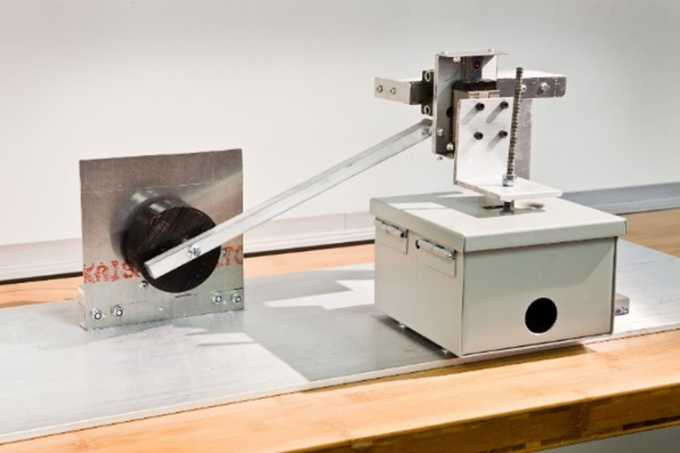
Scrape abrasion test stand.
Test Results
The scrape abrasion test results are shown and discussed in the following sections.
AS22759/34 Scrape Performance
While scrape testing for the AS22759/34 wire is not a specified requirement, it is a very common test procedure called out by OEMs as part of final harness verification. The testing performed here examined the abrasion resistance of the AS22759/34 wire at elevated temperature, in particular, the abrasion resistance at 85°C.
The test results are shown in the accompanying figure. The results show a stark contrast between four of the suppliers and one other (Mfr #4). It is well-established that cross-link ETFE weakens as it is exposed to elevated temperatures, however, it appears as though one manufacturer utilizes a different process for preparing the insulating material than the other four evaluated here. To quantify this performance difference, one supplier (Mfr #4) performed nearly an order of magnitude better than its competitors.
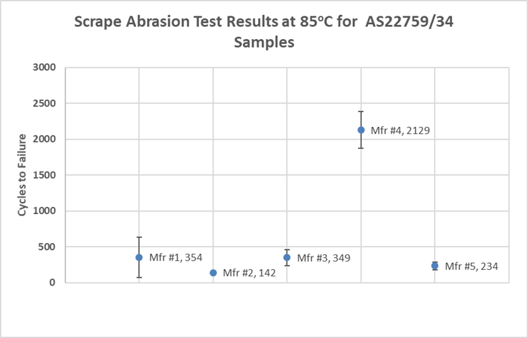
Average and standard deviation of AS22759/34 scrape abrasion test results at 85oC.
While the exact impact on service life cannot be established, it is very likely that the wire produced by Mfr #4 would last significantly longer in a chaffing environment.
AS22759/87 Scrape Performance
The scrape abrasion results for the AS22759/87 specified wires are shown in the accompanying figure. The difference between the suppliers is far less dramatic than the scrape abrasion results for the AS22759/34 wire discussed in the previous section.
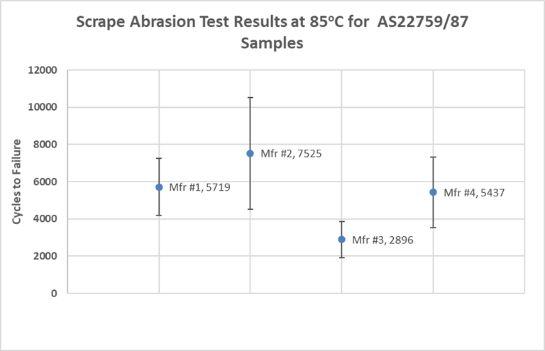
Average and standard deviation of AS22759/87 scrape abrasion test results 85oC.
Dynamic Cut Through
One of the most common means for damage to wire/cable on an aircraft is when the wire/cable is crushed. This may happen by a misaligned LRU, accidental contact by maintenance, or any other way a wire/cable may be pinched when in-service. A wire/cable’s ability to withstand compression damage, particularly at elevated temperatures, will likely correspond to fewer physical damage related issues.
The dynamic cut-through test is designed to assess the cut-through force of a wire/cable specimen. The wire/cable specimen is compressed under the fine edge of a jig until contact is made between the wire/cable conductor and the test jig. The pass/fail criteria for this test is based on the wire/cable’s specification.
Test Information
- Test Specification: AS4373-D
- Method: 703
- Test Parameters: See the following table
Dynamic cut through test properties.
|
Property |
Measured Value |
Accuracy |
|
Travel Distance |
0.00” – 5.00” |
± 0.005 |
|
Rigid Needle Diameter |
0.5 mm |
± 0.03 mm |
|
Elevated Test Temperature (if applicable) |
20oC – 260oC |
± 3oC |
|
Applied Force |
0 – 2500N |
± 0.05N |
In this test, the sample is placed under a compression force tester. Either the insulation of the primary wire or all wires and the shield are connected to a detection circuit to identify when contact is made between the sample and the cut through jig.
[Left] the cross-section of the wire is shown with the clean jig applying force perpendicular to the lodging to the direction of the sample. [Right] the cut through jig with the steel needle is shown.
AS22759/34 Cut Through Performance
The results for the dynamic cut through of AS22759/34 are shown in the following figure. Similar to the results found in the scrape abrasion tests, four of the wire manufacturers had very similar results whereas one manufacturer had measurably better results. Manufacturer number two had an average dynamic cut through value about two times that of the other four manufacturers. In application, this would likely result in manufacturer #2 wire enduring more physical damage without failure.
Cut-through resistance of AS22759/34 at 70oC.
AS22759/87 Cut Through Performance
The results of the AS22759/87 results are shown in the following figure. The data spread of each sample was comparatively small with each showing very consistent results.
Three of the wire manufacturers had very similar results with average dynamic cut through values near 30 lbs. One manufacturer (Mfr #1) had an average dynamic cut through performance of 65 lbs which is more than twice of the other tested samples. Review of the test setup did not identify and variation with the test performance.
Cut-through resistance of AS22759/87 at 200oC.
A positive note from the AS22759/87 evaluation is that all of the samples performed above the minimum dynamic cut through requirements of 15 lbs. at 200°C.
Flexibility
The flex test is performed to assess the capability of a conductor to withstand repeat mechanical flexing until complete break of the conductor. Test performance will not provide an estimate on service life but can be used as a comparative test between comparable wire types.
Test Information
All samples had the same weight attached and were bent around the same size of mandrel to allow a comparative basis for samples. The mandrels were held in place with a defined separation (Figure 7).
- Test Specification: EN3475
- Method: 512
- Test Parameters: See the following table
|
Property |
Measured Value |
Accuracy |
|
Fixed Mandrel Separation Distance |
0.01” – 1.00” |
± 0.005 |
|
Rotation Speed |
18 CPM |
± 1 CPM |
|
Ambient Test Temperature |
20oC |
± 3oC |
|
Static Weight |
5 lbs. |
± 0.1 lbs. |
Configuration of flex test
The European flex test method was selected for this evaluation because:
- The time necessary to complete is much less than the AS4373 variant.
- Fewer trials are needed than the AS4373 variant
- In Lectromec’s experience, a wire performing well in the AS4373 version of the flex test will also perform well in the EN 3475 version.
AS22759/34 Flexibility Performance
The test results of AS22759/34 are shown in Figure 8. The test results for the AS22759/34 wires are fairly consistent, with an average across the entire group of 430 cycles to failure. While there is some variation between the manufacturers, the of performance is much less than found in scrape abrasion and the dynamic cut through results discussed in the previous sections.
Flex test results of AS22759/34 wires.
There does not appear to be an appreciable difference between the AS22759/34 wire manufacturers for this test.
AS22759/87 Flexibility Performance
The results of the AS22759/87 wires are shown in Figure 9. The results show more variance between manufacturers than the AS22759/34 wires. One manufacturer (Mfr #2), had a much wider data spread than any of the other wires tested in this effort. Review of the specimen did not provide any identifiable differences between the specimen that performed well and those that performed poorly.
Flex test results of AS22759/87 wires
Conclusion
The testing performed by Lectromec showed variability in standardized qualified wires. While the components tested do perform above the minimum performance requirements established in the product specifications, there are manufacturers that have developed products that go above and beyond the minimum requirements. In some cases, the performance difference is an order of magnitude, and others, the performance difference is a factor of 2 to 5.
There are more tests that can be performed on each of the samples, in particular the performance after long-term environmental exposure is always of interest. Lectromec believes that it is likely that many of the other tests yielding non-boolean results would further differentiate the wires tested.
In application, wire harness fabrication shops and OEMs should not take qualified products for granted. The limited testing performed here shows a clear differentiation between the performance of standardized qualified products. While the testing was performed under lab conditions, it does represent the failure modes most common in aircraft electrical wiring interconnect systems (EWIS).
As such, comparative performance testing should be part of any wire/cable acceptance program. To simply say that a wire or cable is a qualified part ignores the potential performance differences between various manufacturers. For those looking to make this part of their part selection/verification process, contact Lectromec.

Michael Traskos
President, Lectromec
michael.traskos@lectromec.comMichael has been involved in wire degradation and failure assessments for more than a decade. He has worked on dozens of projects assessing the reliability and qualification of EWIS components. Michael is an FAA DER with a delegated authority covering EWIS certification and the chairman of the SAE AE-8A EWIS installation committee.