The development and use of coaxial cables have come a long way since its invention in 1880. Improvements in design and reliability have made it a frequent feature for aircraft data transmission applications. In the realm of aerospace, a common coaxial specification is the MIL-DTL-17 coaxial cable standard.
There are several parts to the MIL-DTL-17 (currently at revision H) standard of which application engineers and EWIS designers should be aware. Certainly, the requirements of coaxial cables have evolved as the needs of airborne applications have changed (the military Assist website only have revisions dating back to 1983, and this is revision F). This article provides information on what the cables in this standard are, and characteristics that you should be aware of when selecting or maintaining these cables.
Overview
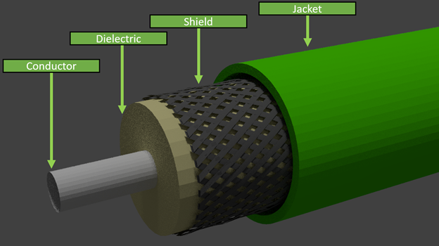
Example coaxial cable.
The MIL-DTL-17 standard covers signal cables specifically designed for “low-loss, stable operation from the relatively low frequencies through the higher frequencies in the microwave and radar regions of the frequency spectrum.” (note: for those unfamiliar with cable specifications, there is typically a based standard, such as MIL-DTL-17, that contains general information, then there are ‘slash sheets’, which are specific cable constructions that fall into the generalized category of the base standard). Specifications, such as the MIL-C-17/185C, are recommended for use up to 1GHz. Whatever the particular use might be, the typical construction of the coaxial cable is the following:
- Jacket: The cable jacket is the outside most surface of the coaxial cable. The jacket is typically made of a tough, flexible, and non-hygroscopic material. There are several material types that are specified in MIL-DTL-17 which include: PVC, Neoprene, Silicone impregnated fiberglass, PTFE, FEP, ETFE, PFA, Polyolefin. The use of the particular jacketing material should be based on environmental and mechanical conditions on the aircraft.
- Shield: The shield is immediately under the cable jacket and is a conductive layer for EMI protection. The shielding is further discussed in the following section.
- Dielectric Core: The dielectric core is used to maintain a consistent dielectric material between the inner conductor and the shield. The consistent shape and uniformity of the dielectric core material is important for stability of the electrical signals carried in the cable. As one might suspect, there are several types of approved dielectric cores in MIL-DTL-17. Many of the modern slash sheets for the MIL-DTL-17 specification use an air-spaced polyethylene material as the dielectric core.
- Conductor: This core conductor is the primary signal carrier for the cable. Depending on the particular MIL-DTL-17 slash sheet selected, the conductor can be made of any one of several permitted conductor types ranging from bare copper to annealed copper-clad steel wire.
Shielding
As discussed earlier, the primary reason for these cables is for signal transmission. This might be for data between devices in the aircraft or for signal antennas. Either way, proper shielding of the cables ensures good system performance. Past Lectromec articles on shielding for cables have covered the different types of shielding and the potential impacts of EMI.
Flammability
An interesting item about the MIL-DTL-17 cables is that flammability, while it has been in the standard for several iterations, has not always been a requirement of the standard until now. Several of the coaxial cables in the standard, such as MIL-C-17/77 and MIL-C-17/78 do not have flammability requirement (note: these are now inactive standards, but they can still be found on aircraft). For those using these cables, it is advised to consider the risk associated with these cables and determine if a replacement is necessary at the next opportunity.
The flammability test that is called out for in the MIL-DTL-17 is the same 60o burn test as identified in other standards (more can be read here).
Impedance Matching
One item to note with these cables is that, as with any signal cable, impedance matching is very important. For those unfamiliar with impedance matching, anytime there is a break in the circuit, such as at connection devices, the impedance of the mating, if not done properly, can have a significant impact on the signal strength. Slight impedance changes can dissipate the signal energy or reflect it and reduce the overall signal strength to the target device. Identification of these circuit interrupts can be done with Time Domain Reflectometry (TDR) technologies.
This long aside has been made for the purpose of highlighting the importance of selecting cables that match the impedance of the application and not using just whatever is convenient or cheaper. Not all cables are the same and care should be taken when evaluating which cable to use for aircraft design.
Verification Tests
As with any aerospace cable, there are a lot of qualification and verification tests necessary for acceptance and many of these tests are the same as the standard single conductor wires. The following is a brief list of common qualification tests performed on coaxial cables:
- Velocity of propagation
- DC resistance
- Conductor elongation
- Eccentricity
- Aging stability
- Cold bend
- Dimensional stability
- Acid gas generation
- Weathering
- Abrasion resistance
- Tear strength
- Heat distortion
- Hot oil immersion
- Spark test
- Voltage withstand
- Corona extinction voltage
- Attenuation
Application Notes
When using these materials, there are several limitations:
- Flexibility: most of the coaxial cables are not designed for regular flexing applications as a change in the cable shape can impact signal quality
- Limited temperature range: Whereas may of the AS22759 family of wires are rated to 150C and above, 85C is a common threshold temperature for these cables. As such, the possible applications are limited, particularly near engines.
- Maintainability: Coaxial cables have historically been a challenge for repair on aircraft. The dielectric must be repaired with great care and the shield rejoined such that there is no change in the electrical properties. There are coaxial splices and repair tools available, but practice is necessary to ensure the splice is performed correctly.
Summary
Coaxial cables are a critical part of the EWIS design and will continue to be for quite some time. The selection and use of coaxial cables for each application should be carefully considered as there are a lot of choices and it is important to pick the correct one. If you have a need for guidance on part selection, EWIS certification, or EWIS component testing, contact Lectromec.

Michael Traskos
President, Lectromec
michael.traskos@lectromec.comMichael has been involved in wire degradation and failure assessments for more than a decade. He has worked on dozens of projects assessing the reliability and qualification of EWIS components. In September 2014, Michael was appointed as an FAA DER with a delegated authority covering EWIS certification.