View Latest Blog Entries
Close
Categories
Testing & Assessment Certification Standard & Regulation Aging Wires & Systems Maintenance & Sustainment Management Conference & Report Protection & Prevention Research Miscellaneous Arcing
Popular Tags
Visual Inspection High Voltage AS50881 MIL-HDBK MIL-HDBK-525 FAR AS4373 Maintenance Electromagnetic Interference (EMI) FAR 25.1707 Wire System Arcing Damage
All Tags in Alphabetical Order
2021 25.1701 25.1703 abrasion AC 33.4-3 AC 43 Accelerated Aging accessibility ADMT Aging Systems AIR6808 AIR7502 Aircraft Power System aircraft safety Aircraft Service Life Extension Program (SLEP) altitude arc damage Arc Damage Modeling Tool Arc Fault (AF) Arc Fault Circuit Breaker (AFCB) Arc Track Resistance Arcing Arcing Damage AS22759 AS22759/87 AS23053 AS29606 AS4373 AS4373 Method 704 AS50881 AS5692 AS6019 AS6324 AS81824 AS83519 AS85049 AS85485 AS85485 Wire Standard ASTM B355 ASTM B470 ASTM D150 ASTM D2671 ASTM D8355 ASTM D876 ASTM F2639 ASTM F2696 ASTM F2799 ASTM F3230 ASTM F3309 ATSRAC Attenuation Automated Wire Testing System (AWTS) Automotive Avionics backshell batteries bend radius Bent Pin Analysis Best of Lectromec Best Practice bonding Cable Cable Bend cable testing Carbon Nanotube (CNT) Certification cfr 25.1717 Chafing Chemical Testing Circuit Breaker circuit design Circuit Protection cleaning clearance Coaxial cable cold bend collision comparative analysis Compliance Component Selection Condition Based Maintenance Conductor Conductor Testing conductors conduit Connector Connector rating connector selection connector testing connectors contacts Corona Corrosion Corrosion Preventing Compound (CPC) corrosion prevention Cracking creepage D-sub data analysis data cables degradat Degradation Delamination Derating design safety development diagnostic Dielectric breakdown dielectric constant Dimensional Life disinfectant Distributed Power System DO-160 dry arc dynamic cut through E-CFR electric aircraft Electrical Aircraft Electrical Component Electrical Power Electrical Testing Electrified Vehicles Electromagnetic Interference (EMI) Electromagnetic Vulnerability (EMV) Electrostatic Discharge EMC EMF EN2235 EN3197 EN3475 EN6059 End of Service Life End of Year Energy Storage engines Environmental Environmental Cycling environmental stress ethernet eVTOL EWIS certification EWIS Component EWIS Design EWIS Failure EWIS sustainment EWIS Thermal Management EZAP FAA FAA AC 25.27 FAA AC 25.981-1C FAA Meeting failure conditions Failure Database Failure Modes and Effects Analysis (FMEA) FAQs FAR FAR 25.1703 FAR 25.1707 FAR 25.1709 Fault fault tree Fixturing Flammability fleet reliability Flex Testing fluid exposure Fluid Immersion Forced Hydrolysis fuel system fuel tank ignition Functional Hazard Assessment functional testing Fundamental Articles Fuse Future Tech galvanic corrosion Glycol Gold Gold plating Green Taxiing Grounding hand sanitizer handbook Harness Design harness protection hazard Hazard Analysis health monitoring heat shrink heat shrink tubing high current high Frequency high speed data cable High Voltage High Voltage Degradation HIRF History Hot Stamping Humidity Variation HV connector HV system ICAs IEC 60851 IEC60172 IEEE immersion insertion loss Inspection installation installation safety Instructions for Continued Airworthiness insulating material insulating tape Insulation insulation breakdown insulation resistance insulation testing interchangeability IPC-D-620 ISO 17025 Certified Lab ISO 9000 J1673 Kapton Laser Marking life limit life limited parts Life prediction life projection Lightning lightning protection liquid nitrogen lithium battery lunar Magnet wire maintainability Maintenance Maintenance costs Mandrel mean free path measurement mechanical stress Mechanical Testing MECSIP MIL-C-38999 MIL-C-85485 MIL-DTL-17 MIL-DTL-23053E MIL-DTL-3885G MIL-DTL-38999 MIL-E-25499 MIL-HDBK MIL-HDBK-1646 MIL-HDBK-217 MIL-HDBK-454 MIL-HDBK-516 MIL-HDBK-522 MIL-HDBK-525 MIL-HDBK-683 MIL-STD-1353 MIL-STD-1560 MIL-STD-1798 MIL-STD-464 MIL-T-7928 MIL-T-7928/5 MIL-T-81490 MIL-W-22759/87 MIL-W-5088 MIL–STD–5088 Military 5088 modeling moon MS3320 NASA NEMA27500 Nickel nickel plating No Fault Found OEM off gassing Outgassing Over current Overheating of Wire Harness Parallel Arcing part selection Partial Discharge partial discharge at altitude Performance physical hazard assessment Physical Testing polyamide polyimdie Polyimide-PTFE Power over Ethernet power system Power systems predictive maintenance Presentation Preventative Maintenance Program Probability of Failure Product Quality PTFE pull through Radiation Red Plague Corrosion Reduction of Hazardous Substances (RoHS) regulations relays Reliability Research Resistance Revision C Rewiring Project Risk Assessment S&T Meeting SAE SAE Committee Sanitizing Fluids Secondary Harness Protection separation Separation Requirements Series Arcing Service Life Extension Severe Wind and Moisture-Prone (SWAMP) Severity of Failure shelf life Shield Shielding Shrinkage signal signal cable Silver silver plated wire silver-plating skin depth skin effect Small aircraft smoke Solid State Circuit Breaker Space Certified Wires Splice standards Storage stored energy superconductor supportability Sustainment System Voltage Temperature Rating Temperature Variation Test methods Test Pricing Testing testing standard Thermal Circuit Breaker Thermal Endurance Thermal Index Thermal Runaway Thermal Shock Thermal Testing tin Tin plated conductors tin plating tin solder tin whiskering tin whiskers top 5 Transient Troubleshooting TWA800 UAVs UL94 USAF validation verification video Visual Inspection voltage voltage differential Voltage Tolerance volume resistivity vw-1 wet arc white paper whitelisting Winding wire Wire Ampacity Wire Bend Wire Certification Wire Comparison wire damage wire failure wire performance wire properties Wire System wire testing Wire Verification wiring components work unit code

MIL-HDBK-683: Techniques for effectively analyzing data

Testing & Assessment

Failure analysis and system reliability are a fundamental part of the aerospace industry. With the extremely rare exception, modern aircraft are assessed and evaluated at the component, system, and aircraft level for all manner of failure impacts. This article will give methods for effectively analyzing data and discuss the commonly accepted Failure Mode and Effects Analysis (FMEA) technique as it is applied to the Electrical Wire Interconnect System (EWIS) for aerospace, using MIL-HDBK-683 as a guide.

As the title implies, the MIL-HKBK-683 is a set of guidelines the military uses to discuss tools and analytical techniques used for effective decision making. Although MIL-HDBK-683 is primarily focused on process improvement, the particular application will have industry specific language describing the means of assessing failure modes common across industries.

FMEA is a common qualitative analysis tool developed in the 1940s for failure analysis that requires an in-depth analysis of all sub-systems for the purpose of identifying potential failure modes as well as their root causes and effects. In this assessment, each failure mode is given a probability of detection and a probability of system failure. The following steps can be used as a guideline when performing an FMEA.

1. Identify Failure Modes

Assess all potential failure modes in a system. This requires an in-depth understanding of how each sub-system interrelates and contributes to the whole system. Identification of potential failures can be the most challenging step when performing an FMEA, especially in complex systems where one failure mode can be the cause for another failure mode in another sub-system. When applying FMEA to an aircraft’s EWIS components, there are numerous potential failures that need to be assessed. One common failure mode found on EWIS is harness chafing; it will be used as an example throughout the rest of this article.

2. Root Cause Analysis

Determine the root cause of each failure mode. This step requires an underlying problem assessment. If performed with a new design, this may include the development of a “fishbone style” analysis to examine potential weak points in the design. When looking at EWIS, one common cause for chafing is improper clamp installation. When clamps are installed improperly, the harnesses can have too much room or they can be too tight. In each situation, the harnesses will either chafe on each other or against the clamp causing the harness to deteriorate over time.

Effectively Analyzing Data
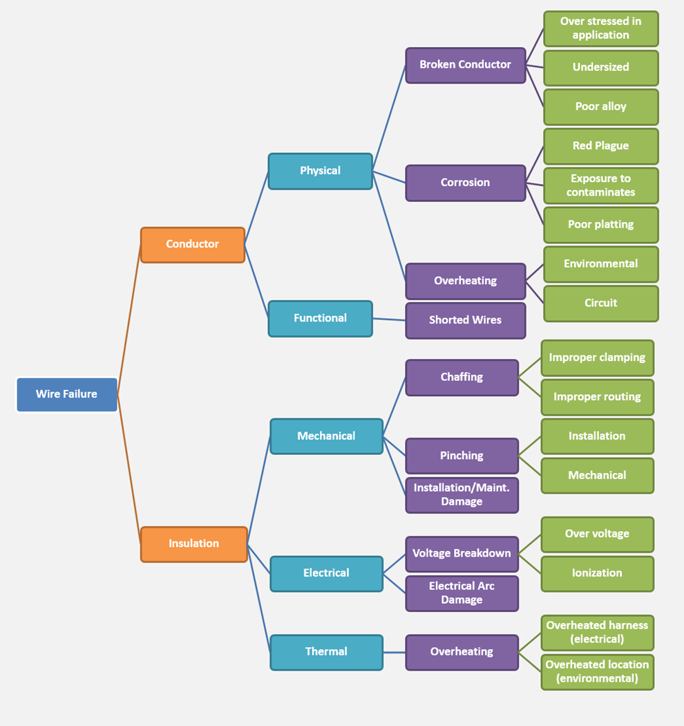
Root cause analysis can take many forms. When investigating wire systems, root cause analysis associated with EWIS will be similar the one presented here.

3. Probability of Failure Occurrence

Calculate the probability of occurrence for each failure mode. If component failure data is not available, then a qualitative scale can be used. For the example here, a scale of 1 to 10 (1 being a very low probability and 10 being a very high probability of occurrence) will be used. Chafing points found on older aircraft are often due to more maintenance and replacement activities. Since it is common to find various chafing points, the score for the probability of occurrence is a high score of 8.

4. Failure Criticality

Estimate the weight or criticality of each failure mode on a scale of 1 to 10 (1 being a very low failure criticality and 10 being a very high failure criticality). For those familiar with FAA AC 25.1701, five severity levels are defined ranging from “No Safety Effect” to “Catastrophic.” In our example, the wire harness being chafed contains some power wires, but mostly low power and signal wires for the In-Flight Entertainment System. While the functional impact due to failure is low, the physical damage may cause damage to structure and other systems. Therefore, chafing will be given a moderate score of 6. For further discussion about EWIS failure criticality, you can read Lectromec’s EWIS Regulatory Compliance with 25.1707 – Part I article.

5. Latent Faults

Estimate the probability of “escaped” defects. Escaped defects are the number of failures that are not detected during system checks, such as an inspection. Being able to detect chafing on harnesses is fairly easy when inspection and maintenance checks are performed on a regular basis. Consequently, the probability of having escaped defects is small resulting in a low rating of 3. This value can be modified if routine maintenance checks are not performed on a regular basis.

6. Risk Priority Determination

Calculate the risk priority number by multiplying the values determined in Steps 3, 4, and 5. The resulting value can be used as a way to prioritize and allocate the necessary resources to mitigate the high-risk potential failures. Mitigation may come in the form of rerouting, secondary harness protection, or reducing the likelihood of failure with regular inspections. If periodic inspections are considered, the FAA has suggested a process called Enhanced Zonal Analysis Procedures (EZAP).

Conclusion

This article summarizes the FMEA analysis discussed in MIL-HDBK-683 as applied to EWIS. This analytical technique can be applied to almost any system for determining potential failures and identifying effective mitigation solutions. For more information on other techniques including design of experiments and cause analysis refer to MIL-HDBK-683. If you are looking for turnkey EWIS risk assessment, you can check out Lectromec’s EWIS Risk Assessment Tool (EWIS RAT).

Carina Cannon

Carina Cannon

Engineer, Lectromec

Carina is a systems engineer with experience in quality management systems, EWIS component degradation modeling, and test equipment design. Carina’s work has focused on EWIS assessment for Service Life Extension Programs (SLEP) and preparing Lectromec’s lab for formal ISO 17025 lab certification which Lectromec received in June 2015.