Preventing Overheating of Wires in Aerospace
In the aircraft industry, a lot of effort goes into thermal management of the electrical wire interconnection system (EWIS). If not effectively managed, systems fail to operate and may lead to failures. A recent example of this is the case with the Boeing 787 battery issues (read the Report on Boeing 787 Dreamliner Battery Flaws Finds Lapses at Multiple Points). The thermal management of the wiring system is just as important as the thermal management of any other aircraft component. But what about thermal management of EWIS on spacecraft?
In the earth’s atmosphere, heat is dissipated in three ways: through convection, conduction, and radiation. Some of these methods can be estimated directly, but the complexity of convection can require more advanced tools for analysis. SAE standard AS50881, Wiring Aerospace Vehicle, gives the accepted aerospace standard for up to an altitude of 100k feet. Theoretical models for in space conditions can more easily give insight into what can be expected from a wire under electrical load than those for in atmospheric conditions.
Two modes of heat transfer need a medium: convection and conduction. Space in general, lacks such medium. For a wire in a space-based application, the only heat transfer mechanisms that can occur are radiative heat loss and conduction along the wire. If we ignore the thermal conduction down the wire to other system components, black body radiation of the wire at elevated temperature can give a good understanding of the wire’s ampacity.
A Wire in Space
Black body radiation of an object is the amount of light energy that is emitted over the whole light spectrum per time for a given temperature. The energy per unit time and surface area, radiated from a system is given by:
E= σT4
where σ is the Stefan-Boltzmann constant and T is the object’s temperature. Multiplying this energy by the surface area per length (circumference) of a wire gives the energy per time (power) being radiated for a given length of wire. From this, we have power dissipated per length of wire.
A wire will cause joule heating (also known as resistive heating) when there is an electrical current on the wire. The electrical energy converted to heat is given by,
P = I2R
where I is the current and R is the resistance of the wire per length. For any closed system at constant entropy (equilibrium), the energy in equals the energy out. So, for a given current on a wire, the wire will heat up due to joule heating until it matches the radiative heat loss. Reference Fig. 1, the curve labeled “space,” for the current and temperature at equilibrium for a 20 gauge wire.
A Wire at Ambient Atmospheric Conditions Varying Altitude
For aerospace applications within the earth’s atmosphere, we reference AS50881. For, a single copper wire, the rationale of AS50881 can be represented by the following formula:
I = HIg(x)
Where I is the maximum allowed current for the wire at the prescribed altitude, Ig is the current of the same gauge wire at standard temperature and pressure, which is a function of the wire’s maximum temperature rating and the ambient temperature of the operational environment. A graph of Ig(x) for various wire gauges and ‘H’ at various altitudes are provided in AS50881 Rev D.
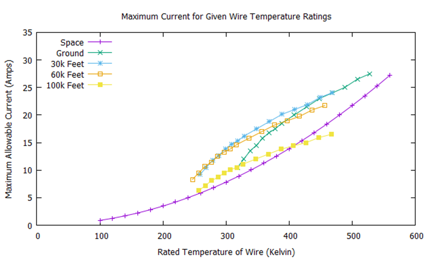
Figure 1: Maximum allowable current for varying temperature ratings for a 20 AWG wire at varying altitudes assuming 20oC
U.S. Standard Atmosphere, 1976 (NASA-TM-X-74335) provides standard ambient temperatures for different altitudes. These ambient temperatures can be used for the operational environment. Reference Table 1 for ambient temperatures at chosen altitudes. Using these ambient temperatures and AS50881, we can generate curves for the maximum allowable current for a given rated temperature of wire. The results of this analysis are in Fig. 1 for four different altitudes for a single 20 AWG wire.
Note: The data above assumes ambient temperatures as the wire’s operational temperatures at altitude. If the wires are in a pressurized, temperature-controlled cabin, these curves must be recalculated based on those operational conditions.
Another challenge that exists is the routing of the wire harness in an enclosed space. If the area is sealed or relatively small, the wire may heat up the local area. When considering the impact of the allowable current, the higher temperature environment causes the curves to shift right.
| Altitude (feet X 1000) | Ambient Temp. (kelvin) |
| 0 | 288.2 |
| 30 | 228.7 |
| 60 | 216.7 |
| 100 | 227.1 |
Table 1: Ambient Temperatures used
Impact of Local Environment
As could be expected, removing the convection heat loss mode results in different maximum temperature profiles between atmospheric and space conditions. The AS50881 standards up to 100k feet rely on a correction factor to ground conditions. If the atmosphere were diffuse enough (at high enough altitude), the curve generated from the space model should take over. This effect might not appear in the rationale of AS50881, because it may be very small up to 100k feet or, if it is large enough to be visible in the phenomena, the altitude correctional factor might be designed to be conservative to allow room between engineering design and the failure mechanism of an overheating wire.
The model in space seems to be a good conservative estimate model for the maximum current allowable. An exception is the 100k feet case, where the curve goes below that of the wire in a vacuum model. In this range, the ozone layer is active and the temperature is higher than expected when compared to a case in which we assume thermodynamic equilibrium between atmospheric altitudes (move air from the ground up to 100k feet adiabatically and you will have a much lower temperature than in ambient conditions at 100k feet).
Conclusion
The operational environment affects the methods for heat loss and cooling of electrical system components. In space, due to a lack of medium required for conduction or convection, radiative heat loss and conduction are the only mechanisms of heat loss along a wire. Ignoring conduction, black body radiation of the wire at elevated temperature can give a good understanding of the wire’s ampacity. In Earth’s atmosphere, under ambient conditions, the wire in a vacuum model can often be used as a conservative ballpark estimate. Operational temperatures can vary greatly from ambient temperatures in applications. If the operational temperature is high, one must choose an appropriately high temperature rating of wire and design an appropriately low current on this wire.

Tristan Epp Schmidt
Engineer, Lectromec
info@lectromec.comSince starting at Lectromec in early 2015, Tristan has been key in many of test and assessment wire systems assessment projects wire systems assessment. His attention to detail has lead to several key insights in Lectromec’s research initiatives.