When electrical current flows down a conductor, it gets warm due to resistive heating. The more current that flows, the warmer the conductor gets. Depending on the wire gauge, conductor conductivity, and ambient temperature of the wire location, the conductor temperature reaches the maximum certified temperature. This maximum electrical current is where the outward heat (through convection and radiation) matches the resistive heating of the conductor (see how this is applied for space applications). This steady state condition is the ampacity of a single wire. The problem becomes more complicated with the addition of more wires and use of different wire types (signal, different wire gauges, conductor types) bundled into the wire harness.
The following article provides a brief overview of developing technology to address harness ampacity and how it can be optimized for Electrical Wiring Interconnection System (EWIS) design.
The Need for Derating
The history of ampacity derating of wire harnesses on aircraft stretches back to 1947 with the first guidelines contained in the Naval Research Lab 3145 standard. The first iterations of ampacity focused primarily on avoiding smoke generation. As the needs of aircraft electrical system increased, so did the focus and complexity of the ampacity model. Decades of improvement in understanding led to the development of the formulations now part of the AS50881 standard.
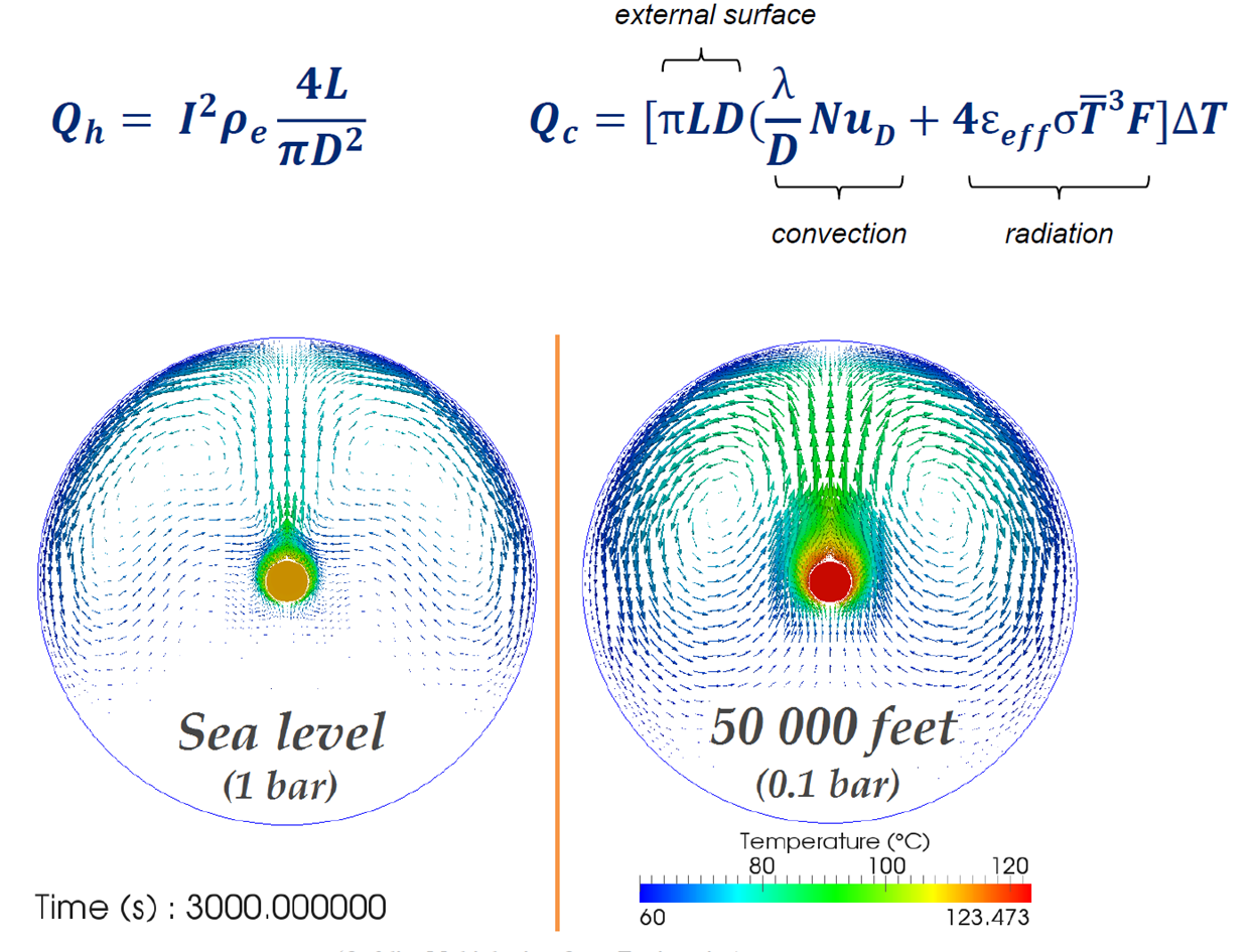
The heat dissipation on a conductor can be approached with a first order approximation using the formula on the left. To get a more accurate result, the formulation on the right also accounts for the more complex convection factor. The two figures presented show how the pressurization can impact the wire temperature. Source: Fokker Elmo
In its current form, the reason that ampacity limits are placed on wires, cables, and harnesses, is to:
- Ensure that the maximum conductor/insulation operational temperature is not violated,
- Maintain the long-term wire/cable reliability, and
- Determine if the use different wire gauges are necessary to meet the system electrical load requirements.
The ampacity calculations, as they are specified in AS50881, will ensure a safe EWIS design (from an overheating perspective); this is validated by decades of aircraft designed with this limitation. However, a thoughtful review of this list finds that none of these items seek an optimum wire harness design. Furthermore, the existing guidance suggests things like secondary harness protection have no impact on the harness temperatures (a parallel would be to say that a person would be equally warm with or without a jacket).
There are better tools available to improve the design.
Modeling Improvements
If a better ampacity model were developed than the one currently identified within AS50881, what are some of the potential benefits of being able to better model the operational temperature of wire/cable? A short list might include:
- Thorough understanding of thermal management needs for zones,
- Capture the impact of secondary harness protection, if any,
- Identify configurations to reduced harness weight, and
- Establish ability to predict service life reliability.
- A combination of Fokker Elmo and Lectromec technologies were presented at the October 2016 Aerospace Electrical Interconnect System Symposium (AEISS) that offers a significant improvement in predicting wire harness temperature and for wire harness design. The Fokker Elmo wire harness thermal model goes well beyond the simple ampacity derating that currently exists in AS50881 with the fully adjustable 3D wire harness model. Based on nearly a decade of research and development, the model can account for many of the common design concerns EWIS designers have had for many years.
Comparing the Results
When the Fokker Elmo wire harness thermal model was compared against new laboratory data and the AS50881 formulas (derating curves that have historically been viewed as being conservative), several interesting points were found.
For a single wire in air, configurations of wire gauge and current were found to underestimate the heat generated during operation of the wires. This means that, for some parts of the AS50881 derating curves, the generated heat is underestimated.
As a further part of the Fokker assessment, they examined the potential impact of secondary harness protection. This harness protection material is often used for chafe protection or in fire zones to protect wire. When tested and modeled by Fokker Elmo, the difference between open and closed wire harness constructions varied as much as 58oC. While a temperature increase should not come as a surprise, this is contrary to what is stated in the AS50881.
The size and configuration of the zones in which the wire harness is routed have an impact on the ambient temperature. Smaller enclosed areas may have a temperature increase to the point that additional harness derating may become necessary.
Configuration and placement of power wires within a wire harness (such as bundle together at the core of the wire harness or placed randomly in the wire harness) can have an impact on the wire harness temperature. For the representative harness presented, a 15oC difference was found between the worst case and best case.
Each of these items were found via the Fokker Elmo model and verified by in-lab testing.
Aging Platforms
Consider the many applications Fokker Elmo’s wire harness thermal model might be applied during the EWIS design process, especially in aging platforms. Once the thermal models have been run, it is likely that multiple ideal wire harness configurations will be identified. Without a clear set of defined benefits for these circuit/harness configurations, selection would be difficult. But there is another assessment that can be used to help with harness selection.
Over that last three decades, Lectromec has developed degradation models for EWIS components. Although each component has its own degradation method, many of these models include parameters for mechanical, thermal, and environmental stressors. With that in mind, it is possible to forecast the long-term reliability of the potential harness designs.
In the following example, five harness configurations were identified each with two primary operational modes: one high power that places a higher current on the wire harness and one standard operation that covers 80-90% of the operational time. While none of the operational configurations violate the maximum temperature of the wire harness design, three of the configurations (#1, #2, and #5) create a more rapid degradation of the EWIS components.
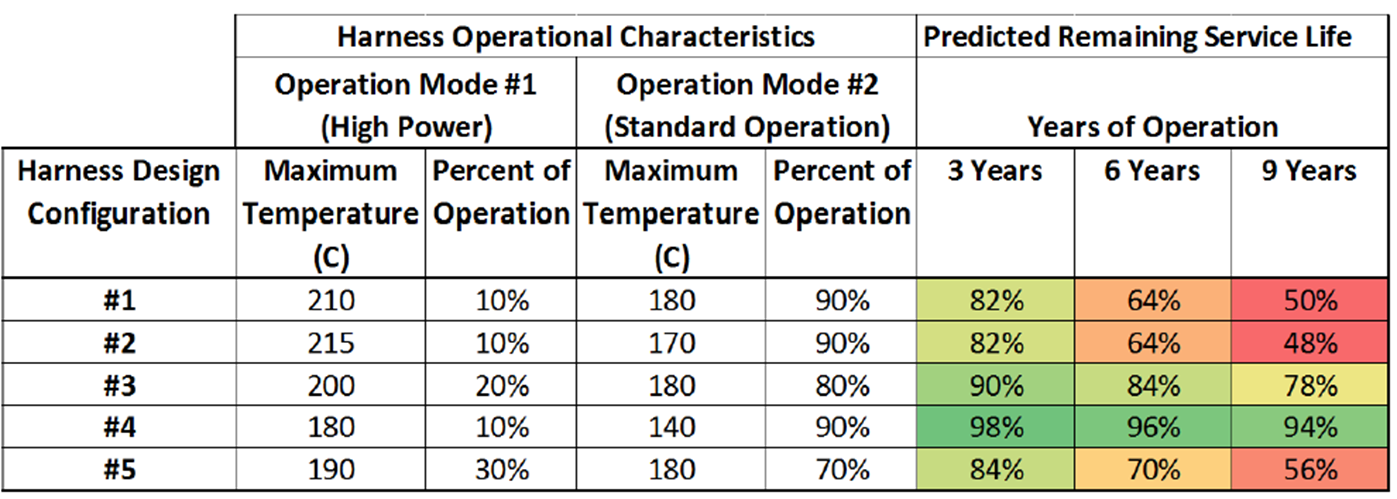
When used for an extended duration at elevated temperatures, wire insulation will degrade. Lectromec’s EWIS degradation models, paired with wire harness temperature predictions, can provide better predictions on long-term performance.
It is not to say that those three options are not viable, but perhaps there is a benefit to these designs such as smaller profile or significant weight savings. However, in making the selection for one of these three configurations also means that harness replacement would be necessary for less than 12 years. By combining the Fokker Elmo thermal modeling with the Lectromec life prediction technology, it is now possible to have the necessary supporting evidence for optimized EWIS design.
Summary
The combination of the Fokker Elmo and Lectromec technologies provides an impressive improvement in wire harness design capabilities. The tools can help designers move away from the sometimes overly conservative ampacity derating of existing standards with precision modeling capabilities and scenario analysis. This creates the opportunity to develop an EWIS that is optimized to the aircraft and meet the needs for long-term performance requirements. To find out more, contact Lectromec.

Michael Traskos
President, Lectromec
michael.traskos@lectromec.comMichael has been involved in wire degradation and failure assessments for more than a decade. He has worked on dozens of projects assessing the reliability and qualification of EWIS components. In September 2014, Michael was appointed as an FAA DER with a delegated authority covering EWIS certification.